Earthworks
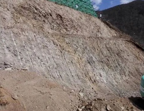
1. The excavation slope is too steep
1.1. Phenomenon:
During earthwork excavation, the slope of the foundation pit and trench after excavation is often steeper than the slope designed in the plan. The lower opening of the slope is not straight, and some of the lower openings are even within the edge of the foundation, which affects the construction of the foundation.
1.2. Prevention and control measures:
1.2.1 Before excavation of foundation pits and foundation trenches, make a written explanation to the on-site construction personnel, explaining the slope and construction sequence of the foundation pit and foundation trench excavation, not only the upper edge of the foundation pit and foundation trench excavation, Use gray lines to release, and also use gray lines to release the lower edge of the foundation pit and foundation trench.
1.2.2 When excavating foundation pits and foundation trenches, first excavate along the gray line at the lower entrance of the foundation pit and foundation trench, and then repair the slope along the gray line at the upper entrance of the foundation pit and foundation trench. When repairing the slope, the slope should be from top to bottom. The soil is excavated in the lower layer, which not only ensures the slope of the foundation pit and foundation trench, but also ensures the straightness of the upper and lower entrances of the foundation pit and foundation trench, and leaves enough 300mm of remaining soil for manual slope repair.
1.2.3 Process supervision and control should be strengthened during construction operations, and any improper construction operations should be corrected immediately.
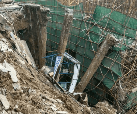
2. Excavation and slope collapse
2.1. Phenomenon:
During or after excavation, the earthwork on the slopes of foundation pits and foundation trenches may partially or extensively collapse or slide, which may affect on-site construction in some cases, or cause quality accidents or casualties in serious cases.
2.2. Prevention and control measures:
2.2.1 The slope of foundation pits and foundation trenches shall be excavated strictly by the slope specified in the construction organization design. For foundation pits and foundation trenches with deep foundations or soft soil, the slope of the slope shall be appropriately enlarged or supported and protected. deal with.
2.2.2 When excavating foundation pits and foundation trenches, the soil should be piled strictly within 5 meters of the upper openings of foundation pits and foundation trenches. On-site construction machinery is not allowed to drive beside foundation pits and foundation trenches to avoid increasing the risk of increasing the slope of foundation pits and foundation trenches: force and vibration.
2.2.3 For uneven soil quality, grading should be carried out at different slopes according to the soil quality of the soil layer.
2.2.4 When the landslide is small, the collapsed soil should be cleaned up in time and provided with appropriate support. For large-scale landslides, the excavation slope must be reinforced and construction can be carried out only after reliable safety guarantees are available.
2.2.5 After the foundation pit and foundation trench are excavated, retaining walls and drainage ditches should be built around the foundation pit and foundation trench in time to drain the water above the foundation pit and foundation trench in time to avoid soaking the slope and cause the slope to become wet. trap.
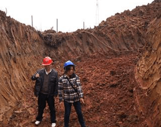
3. Over-excavation of foundation pits and trenches
3.1. Phenomenon:
The main types of over-excavation of foundation pits and trenches include:
3.1.1 The scope of excavation exceeds the excavation edge line.
3.1.2 The depth of excavation exceeds the designed base elevation.
3.2. Prevention and control measures:
3.2.1 The excavation edge lines of foundation pits and foundation trenches should reveal both the upper opening and the base edge line of the excavation. The base edge line should be excavated first, then the slope should be built according to the upper edge edge.
3.2.2 After the sidelines of the foundation pit and trench excavation are laid out, review should be strengthened and strict positioning should be carried out. Excavation should be carried out only after verification is correct.
3.2.3 When mechanical excavation, sufficient remaining soil at the base should be left, and the elevation of the base excavation should be measured at any time to avoid over-excavation.
3.2.4 For over-excavation of earthwork, such as large-area over-excavation, the base elevation should be appropriately changed after obtaining the consent of the design institute, or graded sand and gravel should be used for backfilling.
3.2.5 If local over-excavation occurs, graded sand and gravel can be used to backfill the area with Panax notoginseng lime soil for tamping.
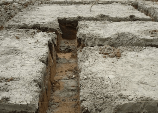
4. The base soil is disturbed or damaged by freezing
4.1. Phenomenon:
After the foundation pit and trench are dug, part or most of the surface layer of the foundation soil becomes loose, or the foundation soil suffers freezing damage during winter construction, and the original soil structure is damaged, resulting in a reduction in bearing capacity and sinking of the foundation soil.
4.2. Prevention and control measures:
4.2.1 After the foundation pit and trench are dug, concrete cushions should be poured immediately to protect the foundation. When the next construction process cannot be carried out immediately, 200mm of soil should be reserved without excavation until the next process begins.
4.2.2 When mechanical excavation, the excavation should be from deep to shallow, leaving sufficient thickness for manual soil removal to avoid mechanical disturbance of the foundation soil. After the foundation pit and trench are dug, machines should be strictly prohibited from driving on them.
4.2.3 Drainage and precipitation measures should be taken around foundation pits and trenches to prevent rainwater soaking.
4.2.4 During winter construction, if the foundation pit or trench cannot be poured with cushion concrete immediately, the surface should be covered with plastic film and cotton felt to prevent the base soil from freezing.
4.2.5 The disturbed base soil should be removed and replaced with lime soil or sand and gravel.
5. Earthwork backfilling and sinking
5.1. Phenomenon:
After the earthwork is backfilled, after some time or a rainy season, cracks and subsidence will appear on the surface of the backfill soil, and hollowing will appear in the ground cushion.
5.2. Prevention and control measures:
5.2.1 Choose better soil materials for backfilling. When the soil contains organic impurities such as tree roots and grass, it should be screened.
5.2.2 When backfilling earthwork, the optimal moisture content of the soil should be controlled. When the soil is too wet, it should be properly dried or mixed with dry soil. When the soil is dry, water should be sprinkled appropriately.
5.2.3 Backfill soil should be constructed in order from low to high. The thickness of the layers should be strictly by the thickness specified in the specification, and the number of compaction passes of the backfill soil should be strictly controlled. After compaction, samples should be taken for testing in time. Construction of the first layer should be carried out only after passing the test.
5.2.4 The backfill soil should have a drainage slope at all times. It should be covered when it rains and the rainwater should be drained away in time.
5.2.5 For backfilling during winter construction, the ice and snow in the soil should be cleared away, and frozen soil blocks are strictly prohibited for backfilling.
5.2.6 After the concrete cushion on the ground is hollowed out, the cushion should be seriously removed, the backfill soil should be compacted again, and the 30-50mm thick soil below the cushion should be changed to Panax, not ginseng soil to increase the bearing capacity of the backfill soil. If the floor tiles have been constructed, pressure grouting can be used to fill the gaps under the backfill and cushion to enhance the backfill’s compactness and increase the base layer’s bearing capacity.
Pile Foundation Project
1. Hammering prefabricated piles – the pile deflection is too large
1.1. Phenomenon:
After the piles were completed, after inspection and acceptance, the pile position deviation exceeded the specification requirements.
1.2. Prevention and control measures:
1.2.1 The site needs to be leveled before construction, and its unevenness should be controlled within 1%.
1.2.2 When inserting piles and starting pile sinking, control the verticality of the pile body within 1/200 (0.5%) of the pile length. If any non-compliance with the requirements is found, correct it in time.
1.2.3 The pile foundation axis control points and leveling points should be located where construction will not affect them. They should be properly protected before the start of construction and after review, and should be retested frequently during construction.
1.2.4 When constructing in saturated soft soil, the pile sinking rate must be strictly controlled. Necessary drainage measures shall be taken to reduce the extrusion and deviation of adjacent piles.
1.2.5 Select a reasonable sequence of pile sinking according to the characteristics of the project.
1.2.6 When connecting piles, ensure that the upper and lower pile sections are on the same axis, and the quality of the joints meets the design requirements and construction specifications.
1.2.7 Before sinking the pile, the obstacles under the pile position must be cleared. If the pile body is found to be tilted, it should be investigated, analyzed, and corrected promptly.
1.2.8 When it is found that the pile position deviation exceeds the specification requirements, it should be studied and handled together with the designer.
2. Hammering prefabricated piles – damage to pile joints
2.1. Phenomenon:
During pile sinking, the pile joints are pulled apart, cracked, or tilted and misaligned.
2.2. Prevention and control measures:
2.2.1 When connecting piles, impurities, and oil on the connecting parts must be cleaned to ensure that the connecting parts are clean.
2.2.2 When using sulfur cement to connect piles, the cement mix ratio should be determined by testing. Strictly follow the operating procedures. The cement in the clamp must be fully poured. The rest time after the cement is poured is generally about 15 minutes. Watering is strictly prohibited to lower the temperature to ensure that the sulfur cement reaches the design strength.
2.2.3 When using the welding method to connect piles, align the upper and lower piles vertically to ensure they are on the same axis. The gap between the two pile sections should be filled with iron sheets to ensure that the surface is flat and vertical, and the welds should be continuous and full to meet the design requirements.
2.2.4 When using flange bolts to connect piles, keep them flat and vertical, tighten the nuts, hammer them several times, and then tighten them again.
2.2.5 After the pile connection is completed, hammer it several times and check again to see if there are any open welds, loose bolts, or cracks in the sulfur cement. If any occur, measures should be taken immediately, and they can be used only after remediation. If repair welding is required, retighten the bolts and use electric welding to seal the nuts or deburr the threads.
3. Hammering prefabricated piles – crushing the pile heads
3.1. Phenomenon:
When prefabricated piles are hammered, the concrete at the pile head breaks and falls off, and the steel bars at the top of the pile are exposed.
3.2. Prevention and control measures:
3.2.1 The concrete strength grade should not be lower than C30, the piles should be vibrated and compacted when making, and the curing period should not be less than 28 days.
3.2.2 The main bars at the top of the pile should be flush to ensure that the concrete is vibrated densely and the thickness of the protective layer is consistent.
3.2.3 When making piles, the concrete protective layer on top of the pile should not be too large, preferably 3cm. Before sinking the pile, conduct a comprehensive inspection and use a triangle ruler to check the flatness of the pile top. Piles that do not meet the requirements of the specification cannot be used or used. It can only be used after processing (repair).
3.2.4 Select a pile hammer according to geological conditions and cross-sectional size. The pile cap is generally 2cm larger than the perimeter of the pile section. If the pile cap is too large or warped and deformed unevenly, it should be processed before construction.
3.2.5 If the pile head is found to be broken, pile sinking should be stopped immediately and the pile pad should be replaced or thickened. If the pile head is severely damaged, the top of the pile should be reinforced and the pile should be driven again.
4. Hammering prefabricated piles – broken piles
4.1. Phenomenon:
During the pile sinking process, the pile body suddenly tilted and dislocated, and the penetration suddenly increased.
4.2. Prevention and control measures:
4.2.1 The concrete strength of piles should not be lower than C30. When making piles, each sub-project should comply with the relevant inspection and evaluation standards. At the same time, there must be a sufficient curing period and correct curing methods.
4.2.2 During stacking, lifting, and transportation, relevant regulations or operating procedures should be followed. When pile cracking is found to exceed the relevant acceptance regulations, use is strictly prohibited.
4.2.3 When connecting piles, the two connected pile sections should be kept on the same axis, and the joint structure and construction quality should comply with the design requirements and specifications.
4.2.4 Before sinking the pile, a comprehensive inspection of the pile components should be carried out. If the bending of the pile body is greater than 1% of the pile length and greater than 20mm, the pile shall not be used.
4.2.5 Before the pile sinks, the obstacles under the pile position should be cleared away. During the initial pile sinking process, if the pile tilts or deviates, the pile should be pulled out and re-pile; if the pile is driven to a certain depth, it may cause damage to the pile. Inclination and deviation must not be corrected by moving the pile frame to avoid bending the pile body; the slenderness ratio of a pile should generally not exceed 40 and can be appropriately relaxed in soft soil.
4.2.6 When piles are broken during construction, they should be handled together with the designer.
5. Hammering prefabricated piles – the pile sinking index does not meet the design requirements
5.1. Phenomenon:
At the end of the pile sinking, the depth and penetration of the pile tip into the soil did not meet the design requirements.
5.2. Prevention and control measures:
5.2.1 Verify the geological report and conduct additional surveys if necessary.
5.2.2 Before formal construction, drive two test piles to check whether the equipment and technology meet the requirements. According to the engineering geological data, combined with the pile cross-section size and shape, pile-driving equipment and pile-driving sequence should be reasonably selected.
5.2.3 Take effective measures to prevent the pile top from being crushed and the pile body from breaking.
5.2.4 When encountering a hard interlayer, a drilling method can be used to drill through the hard interlayer and insert piles into the holes to meet the design requirements.
6. Static pressure pile – pile position offset
6.1. Phenomenon:
The pile displacement exceeds the specification requirements.
6.2. Prevention and control measures:
6.2.1 Before construction, the construction site should be properly treated to enhance the ground endurance; before piling, each pile position should be re-inspected to ensure that the pile position is correct.
6.2.2 Before construction, underground obstacles, such as old wall foundations, concrete foundations, etc., should be cleared. If there is obvious deviation during pile sinking, they should be removed immediately (generally, the pile can be removed within 3m of being inserted into the soil). , wait for re-cleaning before sinking piles.
6.2.3 During the construction process, the pile driver should be kept flat. Construction operations should not be started without the pile driver being leveled.
6.2.4 When serious deviation occurs during construction, it should be studied and dealt with together with the designer. If pile-filling measures are adopted, pile filling should be carried out according to the pile-filling method of prefabricated piles.
7. Static pressure pile – insufficient depth of pile sinking
7.1. Phenomenon:
The pile sinking cannot reach the designed elevation.
7.2. Prevention and control measures:
7.2.1 Before construction, geological drilling data should be verified. Generally, large-tonnage pile drivers should be used.
7.2.2 The pile driver must meet the pile sinking requirements and ensure that the pile driver is in good mechanical condition before construction and during the pile sinking process. Once a fault occurs, it should be repaired in time.
7.2.3 Accept prefabricated piles by design requirements and specifications. Only when the quality is qualified can they be used for pile sinking?
7.2.4 The pile driver must be kept flat and vertical. Once the pile body tilts, no forced correction is allowed.
7.2.5 When there is a hard soil layer or silt sand layer, the pile planting method or the water injection method can be used for construction.
Underground Waterproofing Project
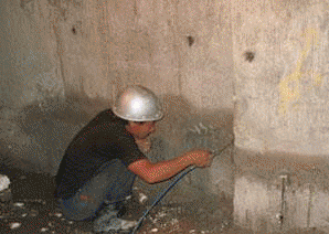
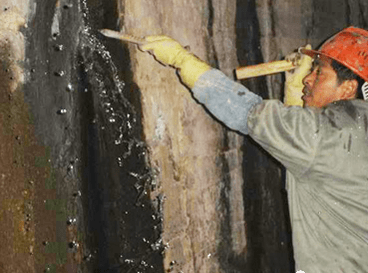
1. Cracks and leaks in concrete walls
1.1. Phenomenon:
Cracks appeared mainly in the vertical direction on the concrete wall, and some cracks leaked due to penetration.
1.2. Prevention and control measures:
1.2.1 If there is no backfill outside the wall, cut the cracks along the cracks and fill the cracks with cyanide slurry or other chemical slurry to seal the cracks.
1.2.2 Strictly control the quality of raw materials, optimize the mix ratio design, improve the workability of concrete, and reduce the amount of cement.
1.2.3 The design should control the length of the underground wall by the requirements of the specifications. Measures should be taken in the design of special-shaped underground structures and underground structures that must be continuous.
1.2.4 The method of watering and curing after covering should be adopted, and the curing time should not be less than that specified in the specification. At the same time, temperature cracks that a sudden drop in temperature may cause should be prevented.
2. Water leakage from construction joints
2.1. Phenomenon:
Water leaks along construction joints.
2.2. Prevention and control measures:
2.2.1 Choose the correct joint form.
2.2.2 Handle the joints: After removing the formwork, use a steel wire brush to brush the joints to remove floating slurry, sweep them clean, and rinse and moisten them. Before pouring concrete, lay about 25mm of 1:2.5 cement mortar on the horizontal joints. Pouring concrete must be carefully vibrated and compacted.
2.2.3 Clean the surface of the flat joint, tear off the isolation paper of the rubber water-stop strip, and paste it on the joint in the middle. The overlap length is not less than 50mm, and then you can continue pouring concrete.
2.2.4 Along the leakage area, cyanide gel, propylene glycol, etc. can be poured to block the leakage channel, and then the inner surface of the construction joint should be painted with cyanide gel slurry, with a width of not less than 600mm.
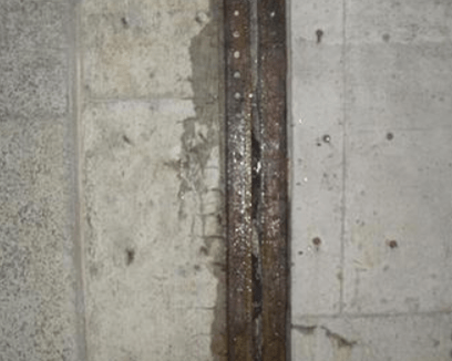
3. Water leakage from deformation joints
3.1. Phenomenon:
The basement is leaking along deformation joints.
3.2. Prevention and control measures:
3.2.1 Use embedded rubber water stops, the quality must be qualified, the lap joints must be filed into a rough slope, and glued firmly with XY-401 glue; the corners of the water stops must be rounded, and must not be Picked up at the corner.
3.2.2 Embed asphalt wood wool boards in the joints, embedded two BW rubber water stop strips on the surface, pasted rubber water stops on them, and then fixed them with pressure plates and bolts.
3.2.3 All rear buried water stops must be removed, BW rubber water stops should be embedded into the bottom of the deformation joints, the water stops should be re-paved, and concrete should be poured and pressed firmly.
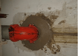
4. Water leakage from wall pipes
4.1. Phenomenon:
Water leaks around the wall pipe.
4.2. Prevention and control measures:
4.2.1 Treatment of concrete leakage under the pipe: Drill the leaking concrete under the pipe to a depth of 250mm. If the water pressure is not high, use fast-hardening cement glue to plug it.
4.2.2 When welding a water-stop ring of 10mm×100mm or above, full welding is required on both sides. When the concrete wall thickness is greater than 500mm, two water-stop rings can be welded.
4.2.3 When pre-embedding a large diameter pipe (diameter greater than 800mm), open a pouring and vibrating exhaust hole at the bottom of the pipe. Concrete can be poured from the hole, and a plug-in vibrator can be inserted into the hole and then vibrated to force air Bleeding water is drained to make the concrete at the bottom of the pipe dense.
4.2.4 Scrub the outside of the pre-pipe clean, paste the BW water-stop strip, tear off the isolation paper, and stick it on the outer pipe with its viscosity. The position is the same as the water-stop ring; when pouring concrete, a dedicated person must be responsible for ensuring the accurate position.
5. Water leakage from post post-pouring belt
5.1. Phenomenon:
Water is leaking along the back pour joints in the basement.
5.2. Prevention and control measures:
5.2.1 Debris on both sides of the post-pouring joint, such as oil stains, etc., must be completely removed; both sides of the concrete must be roughened.
5.2.2 The interval between post-pouring concrete should be between 30 and 40 days after the main structure concrete is completed. It is advisable to choose a season with lower temperatures for construction to avoid concrete cracks due to cold shrinkage. To prepare compensating shrinkage concrete.
5.2.3 Construction must be carried out carefully according to the mix ratio, stir evenly, pour as the mixing goes, vibrate and compact, tap twice, smooth, and wet curing for no less than 7 days.
6. Water leakage due to waterproofing quality issues of the membrane
6.1. Phenomenon:
Leakage occurred inside the basement due to the poor construction quality of the membrane.
6.2. Prevention and control measures:
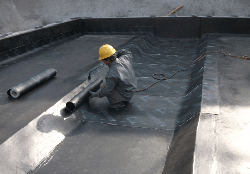
6.2.1 Before the construction of the membrane, the concrete surface should be kept dry and clean. Apply 1-2 coats of cold primer 1-2 days before paving to ensure that the primer does not foam before starting the construction of the membrane waterproof layer.
6.2.2 The corners of the base layer should be made into arc shapes or obtuse angles. The dirt or rust on the surface of the wall-penetrating pipes should be cleaned up, and the coiled materials used at the corners should ensure sufficient elongation, ductility, and good elasticity. toughness. Only after the additional layer of membrane is completed and passed the inspection can the large-area waterproofing membrane be started.
6.2.3 Waterproofing treatment at the pile heads of the basement floor: The steel bars at the pile heads should be sealed with water stops. The piles extend into the cap for at least 50mm. The top of the pile and the area 300mm outside the pile should be compacted and polished with waterproof mortar. Roll The joints around the wood and piles are tightly sealed with polyurethane.
6.2.4 During the construction process, the operation should be carried out strictly according to the requirements of the design and specifications, and sufficient overlap size should be ensured. The waterproof lap joint should be treated with sealing material and sealed tightly along the seams, and the width should be greater than 10mm.
Concrete Project
1. Common quality problems of steel bar raw materials
1.1. Phenomenon:
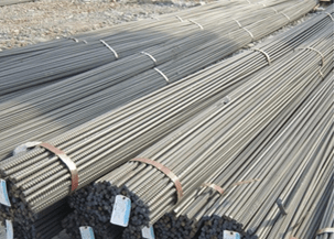
1.1.1 Surface corrosion of steel bars.
11.2 The types and strength levels of steel bars are mixed.
1.1.3 Surface cracks and oblate cross-section of steel bars.
1.2. Prevention and control measures:
1.2.1 Raw steel bars should be stored in warehouses or sheds to keep the ground dry. Steel bars must not be stacked on the ground. They must be padded with concrete or bricks, 200mm above the ground. Steel bars should not be stored for too long. Steel bars stored on site should be Necessary covering measures.
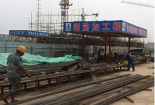
1.2.2 Steel bars of different strengths should be processed separately, and the processed semi-finished products should be marked to avoid misuse. Strength inspection of steel bars should be strengthened during steel bar acceptance to avoid incorrect use.
1.2.3 The steel bars entering the site should be strictly inspected. When quality defects are found, the supplier should be notified in time, and the defective steel bars should be picked out during the processing process. They are strictly prohibited from being used in the main stress-bearing components of the project, such as When there are many defective steel bars, the steel bars should be removed from the site.
1.2.4 After the steel bars are processed, they should be used in the project promptly. Otherwise, the semi-finished steel bars should be covered. When the steel bars have flaky rust, use a wire brush or rust remover to remove rust.
2. Common problems with steel bar processing quality
2.1. Phenomenon:
2.1.1 The strength of cold-drawn steel bars is insufficient.
2.1.2 The elongation rate is unqualified.
2.1.3 The cutting size is incorrect or the cut ends of the steel bars are uneven.
2.1.4 The stirrups are not square and the formed dimensions are inaccurate.
2.2. Prevention and control measures:
2.2.1 Check the material strength of the steel bars, and determine the control stress and cold drawing rate of the steel bars based on the test results. When the strength index is less than the value specified in the technical standards, the cold-drawn steel bars are considered unqualified and must be downgraded or used in non-stressed parts.
2.2.2 The cutting machine should tighten the solid bolts of the length clamp and adjust the horizontal gap between the fixed blade and the punching blade. For the locations of steel bars with inaccurate shearing dimensions and shearing errors, determine whether the steel bars are usable or reworked.
2.2.3 The stirrup cutting list should be re-checked, stirrup samples should be prepared again, and the bending length of each side of the stirrup should be determined. When the stirrup shape error exceeds the allowable value of the quality standard, the best part of the I-grade steel bar can be straightened again and then bent. For other types of steel bars, it is not allowed to be straightened and then bent.
3. Common problems with the quality of reserved steel bars
3.1. Phenomenon:
The reserved steel bars, especially the vertical main bars, are not accurately positioned or the fixing measures are not in place, causing the steel bars to shift, especially the foundation insertion bars of precast shear walls and columns. It is difficult to install the precast shear walls and columns on the first floor. bring great difficulties.
3.2. Prevention and control measures:
3.2.1 Before construction, positioning and setting out should be carried out. Use an ink line to pop up a crosshatch on the bottom of the beam or slab or use cotton thread to fix it on the steel bar to pull out the crosshatch. Then use a steel ruler to measure and determine the position of the vertical steel bar. Calibrate again after the installation and fixation are completed. nuclear.
3.2.2 In the densely reinforced areas of beam nodes and at the junctions of shear walls, columns, and beam tops, add a limit transverse distribution bar or stirrup to the shear wall or column and fix it by spot welding with the stirrups of the beam, and along the wall, column heights are temporarily tied with transverse distribution bars or stirrups with a spacing of no more than 500mm to ensure that the wall and column reinforcements at the nodes will not shift when pouring concrete.
3.2.3 Strengthen the management of on-site concrete pouring. During the concrete pouring process, the rebar inspector must check the position of the steel bars at any time, make timely corrections, and try not to collide with the steel bars. It is strictly forbidden to crush, step on the steel bars, or directly push the steel bars. After the concrete is poured, it should be inspected, corrected, and fixed immediately to prevent deviation.
3.2.4 Position plates should be installed for foundation reinforcements with prefabricated shear walls and columns on the upper floor. The reinforcements should be fixed through the positioning plate holes. The positioning plates should be set 20-50mm away from the concrete surface.
4. Common problems with flash welding quality
4.1. Phenomenon:
4.1.1 Reinforcement joints are bent or eccentric.
4.1.2 The steel bar was burned at the contact point between the steel bar and the electrode.
4.2. Prevention and control measures:
4.2.1 When the steel bar ends are bent, they should be straightened or cut off, and the shape of the electrode should always be maintained. If the deformation is large, it should be repaired or updated in time. When the fixture shakes significantly, it should be repaired in time.
4.2.2 Within the 130mm length of the steel bar end, rust spots and dirt should be removed before welding, the electrodes should be trimmed frequently, and the clamps should be clamped during welding.
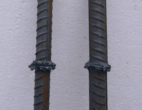
5. Common quality problems of electro-slag pressure welding
5.1. Phenomenon:
5.1.1 The axis offset of the welded joint is greater than 0.1d or 2mm, and the bending angle of the joint is greater than 40°.
5.1.2 The welding package is uneven. There is a lot of molten metal on the large side, and the height of the small side is less than 2mm, or the welding seam formed on the end face of the steel bar is uneven in thickness.
5.2. Prevention and control measures:
5.2.1 Cut off or straighten the uneven ends of the steel bars. The two steel bars clamped in the clamp should be concentric at the top and bottom. When the steel bars are sent down for pressurization, the top pressure should be appropriate and not too large. After the welding is completed, the welding should be stopped for about 2 minutes. Then remove the clamp to prevent the steel bar from tilting.
5.2.2 When the end of the steel bar is tilted too much, the inclined part should be cut off in advance. The amount of melting should be appropriately increased during welding to ensure that the end of the steel bar is melted evenly, and the flux should be filled as evenly as possible.
6. The protective layer of steel bars is too large or too small
6.1. Phenomenon:
6.1.1 When the protective layer of steel bars is detected with instruments, the thickness of the protective layer exceeds the size specified in the design or even exceeds the allowable deviation specified in the specification.
6.1.2 Due to the thin protective layer of steel bars, concrete bars are exposed.
6.2. Prevention and control measures:
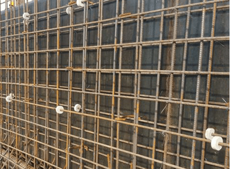
6.2.1 Strictly control the thickness of the protective layer of steel bars in concrete. The bottom bars of beams and slabs are provided with concrete block protective layers or plastic protective cards. The side steel bars of beams and columns use special plastic protective cards as protective layers of steel bars. stool.
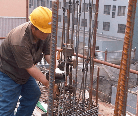
6.2.2 When the main column reinforcements are placed on the floor, the axis of the column reinforcements, the thickness of the protective layer, and the spacing of the column reinforcements must be controlled. Therefore, a welded positioning hoop is tied to the column reinforcements at 20cm and 50cm above the concrete surface of the slab. The main bars and stirrups should be firmly tied to prevent the main bars from shifting after the concrete is poured.
6.2.3 After the steel bars are tied and accepted, the walkways should be paved with bamboo fences or 20cm wide wooden boards on both sides of the pump pipe immediately, and it is strictly forbidden to step on the pedals to load the steel bars.
6.2.4 When leveling the concrete surface, the operator should step on the beam or operate at a place without negative reinforcement, or nail the steel bars on both ends of the wooden board to make a strip, and the operator should operate on the strip when leveling.
6.2.4 Arrange steel bar caregivers during concrete pouring, and repair the steel bars promptly if they are found to be damaged by trampling.
7. Pockmarked concrete surface
7.1. Phenomenon:
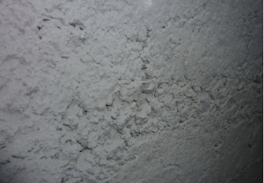
The lack of slurry and many small pits or pits on the concrete surface form a rough surface, which affects the appearance of the surface but does not expose the steel bars.
7.2. Prevention and control measures:
7.2.1 The surface of the formwork should be clean and free of cement mortar, rust, or other dirt.
7.2.2 Before pouring concrete, the formwork should be fully wetted with water, and the debris on the formwork should be washed away. A cleaning opening should be left at the bottom of the column to drain the debris from the formwork.
7.2.3 The template joints should be spliced tightly. If there are gaps, double-sided tape should be used to block the gaps tightly to avoid slurry leakage.
7.2.4 The surface of the formwork should be evenly coated with a release agent before setting up the formwork, and no omissions should be allowed to ensure that an isolation layer is formed between the formwork and the concrete surface.
7.2.4 Concrete formwork should not be removed too early. Especially during winter construction, the removal time of formwork must be controlled to avoid pitting caused by premature formwork removal.
8. The concrete surface is uneven
8.1. Phenomenon:
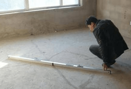
The flatness of the concrete surface is poor, or the thickness of the slab is different, and there are even pits and footprints.
8.2. Prevention and control measures:
8.2.1 Before pouring concrete, check whether the formwork and steel pipe supports meet the design requirements and whether there are inappropriate overhang supports.
8.2.2 The backfill soil of the base layer should be compacted and compacted. Before erecting the shelf, a 200mm wide and 50mm thick wooden board should be laid on the lower part of the steel pipe to increase the stress-bearing area of the support. Drainage ditches should be left around the backfill soil to prevent rainwater from soaking the backfill soil. Add a small amount of water to the formwork before pouring the concrete to prevent the backfill from sinking.
8.2.3 When leveling the concrete, first draw the 50 lines on the frame column steel bars, pull the small white line, and use a scraper to smooth the concrete surface. Use a wooden trowel to level the concrete before it is initially set. Use the scraper to check the concrete surface at any time. Flatness, any uneven areas can be smoothed at any time.
8.2.4 After the concrete is poured, the curing time of the concrete must be ensured. No one is allowed to work until the strength reaches 1.2Mpa. The footprints left by the concrete leveling should be smoothed and compacted.
9. Plastic shrinkage cracks in concrete
9.1. Phenomenon:
Plastic shrinkage cracks, referred to as plastic cracks, mostly appear on the upper surfaces of newly poured foundations, walls, beams, and boards exposed to the air. The shape is close to a straight line, varying in length, incoherent, and the cracks are shallow, similar to dry mud surfaces.
9.2. Prevention and control measures:
9.2.1 When making concrete, the water-cement ratio and cement dosage should be strictly controlled, and well-graded stones should be selected to reduce the void rate and sand rate; at the same time, the concrete should be compacted to reduce shrinkage and improve the early crack resistance of the concrete. strength.
9.2.2 Before pouring concrete, wet the base layer and formwork with water to avoid absorbing moisture in the concrete.
9.2.3 After concrete is poured, the exposed surface should be covered with moist materials in time, and carefully maintained to prevent strong wind and scorching sun exposure.
9.2.4 For construction in weather with high temperature, low humidity, or high wind speed, after concrete pouring, water spraying and curing should be carried out as soon as possible to keep it moist; when concrete is poured in sections, one section should be poured and then cured. In hot seasons, surface wiping and maintenance should be strengthened.
9.2.5 Cover the concrete surface with plastic film or wet straw bags to prevent moisture from evaporating easily.
9.2.6 In windy weather, wind-shielding facilities should be installed to reduce the wind speed acting on the concrete surface.
9.2.7 Treatment method: If the concrete still maintains plasticity, it can be eliminated by pressing it again or vibrating it again in time, and then strengthening the covering and curing. If the concrete has hardened, dry cement powder can be poured into the cracks and then moistened with water, or a thin layer of cement mortar can be applied to the surface for treatment.
10. Concrete drying shrinkage cracks
10.1. Phenomenon:
Dry shrinkage cracks are referred to as dry shrinkage cracks. They are characterized by superficiality, thin width (mostly between 0.05-0.2mm), criss-cross directions, no regularity, and uneven crack analysis.
10.2. Prevention and control measures:
10.2.1 The amount of concrete cement, water-cement ratio, and sand rate cannot be too large; increase the coarse aggregate content to reduce the dry shrinkage.
10.2.2 Strictly control the mud content of sand and gravel and avoid using excessive silt.
10.2.3 The concrete should be vibrated densely, but excessive vibration should be avoided; after the initial setting of the concrete and before the final setting, a second application should be performed to increase the tensile strength of the concrete and reduce the amount of shrinkage.
10.2.4 Concrete should be cured as early as possible and the curing time should be extended appropriately. Concrete exposed to the open air should be backfilled or sealed as soon as possible to avoid excessive humidity changes.
10.2.5 Before pouring concrete, water the base layer and formwork thoroughly to avoid absorbing moisture in the concrete.
10.2.6 After the concrete is poured, the exposed surface should be covered with moist materials in time and carefully maintained to prevent strong wind and scorching sun exposure.
10.2.7 For construction in weather with high temperature, low temperature, or high wind speed, after concrete pouring, water spraying and curing should be carried out in time to keep it moist; when concrete is poured in sections, it is better to finish pouring and curing one section at a time. In hot seasons, surface wiping and maintenance should be strengthened.
10.2.8 Spray curing agent on the concrete surface or cover it with plastic film or wet straw bags to prevent moisture from evaporating easily.
10.2.9 Treatment method: If the concrete still maintains plasticity, it can be eliminated by pressing it again in time or vibrating again, and then strengthening covering and maintenance. If the concrete has hardened, dry cement powder can be poured into the cracks and then moistened with water, or a thin layer of cement mortar can be applied to the surface for treatment.
11. Frost heave cracks in concrete
11.1. Phenomenon:
Cracks of varying widths appear on the surface of structural members along the direction of the main bars and stirrups, with depths generally reaching the main bars, and the surrounding concrete is loose and peeling.
11.2. Prevention and control measures:
11.2.1 When constructing structural components in winter, the concrete should be prepared with ordinary cement, a low water-cement ratio, and a strong anti-winter agent added to improve early strength.
11.2.2 Perform heat storage and insulation or heating curing on concrete until it reaches 40% of the design strength.
11.2.3 Treatment methods: General cracks can be sealed with epoxy cement; for wider and deeper cracks, use epoxy mortar to repair the cracks or add epoxy glass cloth; for more serious cracks, the loose parts should be chiseled away After welding the steel wire mesh, pour a layer of fine stone concrete again and maintain it.
Thank You!
Bored cast-in-place piles have the advantages of low construction noise, and low vibration, pile length…
Bored cast-in-place piles have the advantages of low construction noise, and low vibration,…
The four major construction technologies are dry hole forming technology, slurry static pressure technology, casing…
Soil nail support is a new type of retaining structure developed in recent years for…
Pile Foundation Classification and Construction Principles 1. Classification According to Load-Bearing Piles ① Friction type…
Steel sheet pile cofferdams are suitable for basic projects such as sandy soil, gravel soil,…