Blog

Construction Process Flow Chart for Pile Foundation Work

Section 1: Construction Preparation and Site Leveling

  1. Site Preparation
    • Complete “Three Connections and One Leveling” (water, electricity, road access, and site leveling) before excavation.
    • Remove all obstacles such as underground cables, pipelines, and equipment foundations.
    • Ensure temporary facilities (temporary power, water, safety measures) are ready.
  2. Review Documentation
    • Study construction drawings and geological data (soil and hydrogeological conditions).
  3. Safety Inspection
    • Conduct thorough safety checks on cranes and other equipment before operation.
  4. Site Leveling
    • Level the site according to design elevation requirements.
    • Clear all obstructions (rocks, tree roots, debris) at pile locations.
    • Backfill and compact low-lying areas.

Section 2: Survey and Positioning

  • Establish control points using a total station based on coordinates provided by planning authorities.
  • Verify points with the client and supervisor before proceeding with axis and pile positioning.
  • Use concrete-protected control points to prevent displacement.
  • Conduct initial and secondary pile position checks before and after installing guide sleeves.
  • Drive a Φ12 positioning rebar as a reference for the drilling machine alignment.
  • Verify elevation using a leveling instrument before construction begins.

Section 3: Guide Sleeve Installation

  1. Installation Requirements
    • Center deviation ≤ 20mm, inclination ≤ 1%.
    • Made of 4–8mm steel plate, inner diameter ≥ design pile diameter + 200mm.
    • Equipped with 1–2 overflow holes.
  2. Embedment Depth
    • ≥ 1.5m in clay, ≥ 2.0m in sandy soil.
    • Extend 30cm above ground level.
  3. Purpose
    • Protects the hole opening, guides positioning, isolates surface water, stabilizes slurry level, prevents collapse, and secures the rebar cage.
  4. Cross-Marking for Alignment
    • Set four Φ20 rebar markers in a “+” pattern outside the sleeve for alignment verification.
    • Secure markers with concrete and mark them with red paint for visibility.

Section 4: Drilling Rig Positioning

  • Place the rig on stable sleepers to prevent shifting.
  • Ensure the drill bit center aligns with the guide sleeve (deviation ≤ 20mm).
  • Maintain slurry level ≥ 1m above groundwater (or 1.5m in fluctuating conditions).
  • Impact Drilling Advantages: Effective in gravel layers, enhances hole wall stability, and improves pile bearing capacity.

Mud Pump (3PNL-12 Type)

  • Critical for slurry circulation during drilling.
  • Components: Pump body, impeller, seals, motor, etc.

Section 5: Impact Drilling Process

  1. Initial Setup
    • Fill the guide sleeve with clay and water for slurry formation.
  2. Slurry Requirements
    • Density ≤ 1.25, viscosity 18–20s, sand content ≤ 6%.
  3. Rock Interface & Final Hole Inspection
    • Compare samples with geological reports.
    • Confirm the intermediate weathered tuff layer before final approval.
  4. Drilling Technique
    • Start with low-impact (0.4–0.6m height), then increase to 1.5–2.0m after reaching 3–4m depth.
    • Check verticality every 1–2m; correct deviations immediately.

Section 6: Primary Slurry Cleaning

  • After drilling, circulate slurry to remove sediment.
  • Standards: Sand content ≤ 6%, density ≤ 1.25, sediment thickness ≤ 50mm.
  • Verify the hole depth before proceeding.

Inspection Tools

  • Slurry viscometer, density meter, sediment gauge.

Section 7: Rebar Cage Construction

7.1 Material Inspection

  • Verify supplier certifications, test reports, and mechanical properties.
  • For seismic zones:
    • Tensile-to-yield strength ratio ≥ 1.25.
    • Yield-to-standard strength ratio ≤ 1.3.

7.2 Cage Fabrication

  • Segment per design, with stiffening rings every 2m.
  • Welding: 10d overlap (d = rebar diameter), staggered joints.
  • Use spacer blocks (≥3 per section) for concrete cover.

7.3 Installation

  • Lift with a crane using dual slings to prevent deformation.
  • Align carefully; weld the top support to the guide sleeve.

7.4 Quality Checks

  • Length (±100mm), diameter (±10mm), spacing (±10mm main, ±20mm stirrups), verticality (≤1%).

Section 8: Secondary Slurry Cleaning

  • Remove post-cage sediment via slurry replacement.
  • Final Criteria: Density ≤ 1.25, sand content ≤ 6%, sediment ≤ 50mm.

Section 9: Concrete Pouring

  1. Method: Tremie pipe with bottom-up displacement.
  2. Initial Pour: Ensure 1.0–1.3m pipe embedment to prevent slurry intrusion.
  3. Continuous Pour: Complete within 2–4 hours; no cold joints.
  4. Monitoring: Maintain 2–6m pipe embedment; measure slump (160–220mm).

Section 10: Key Control Points

  1. Pile position verification
  2. Hole depth accuracy
  3. Rock interface confirmation
  4. Secondary cleaning
  5. Rebar quality
  6. Cage welding & placement
  7. Initial concrete pour

Section 11: Common Defects & Solutions

11.1 Position Deviation

  • Cause: Survey or rig misalignment.
  • Fix: Double-check positioning.

11.2 Hole Inclination

  • Cause: Unlevel ground or obstructions.
  • Fix: Compact soil; clear blockages.

11.3 Necking

  • Cause: Collapse or fast pipe extraction.
  • Fix: Optimize slurry; control pipe speed.

11.4 Collapse

  • Cause: Weak slurry or high water pressure.
  • Fix: Use denser slurry; extend sleeves.

11.5 Excess Sediment

  • Cause: Soil fall-in or delayed pouring.
  • Fix: Clean promptly; pour quickly.

11.6 Cage Float

  • Cause: Upward concrete pressure.
  • Fix: Secure cage; slow initial pour.

11.7 Pipe Leak

  • Cause: Insufficient concrete or broken seals.
  • Fix: Ream and repour; check joints.

11.8 Blockage

  • Cause: Poor mix or machine failure.
  • Fix: Vibrate pipe; use backups.

11.9 Buried Pipe

  • Cause: Excessive embedment.
  • Fix: Limit to 6–8m; vibrate gently.

11.10 Broken Pile

  • Cause: Slurry intrusion or bad concrete.
  • Fix: Ensure continuous pour; test mix.

Section 12: Pile Testing

  • Methods: Low-strain integrity test, static load test (per JGJ 106-2003).
  • Scope: 100% integrity check; ≥1% load tests (min. 3 piles).
wedadmin

Recent Posts

10 Major Reasons and 9 Major Control Measures Affecting the Quality of Bored Piles

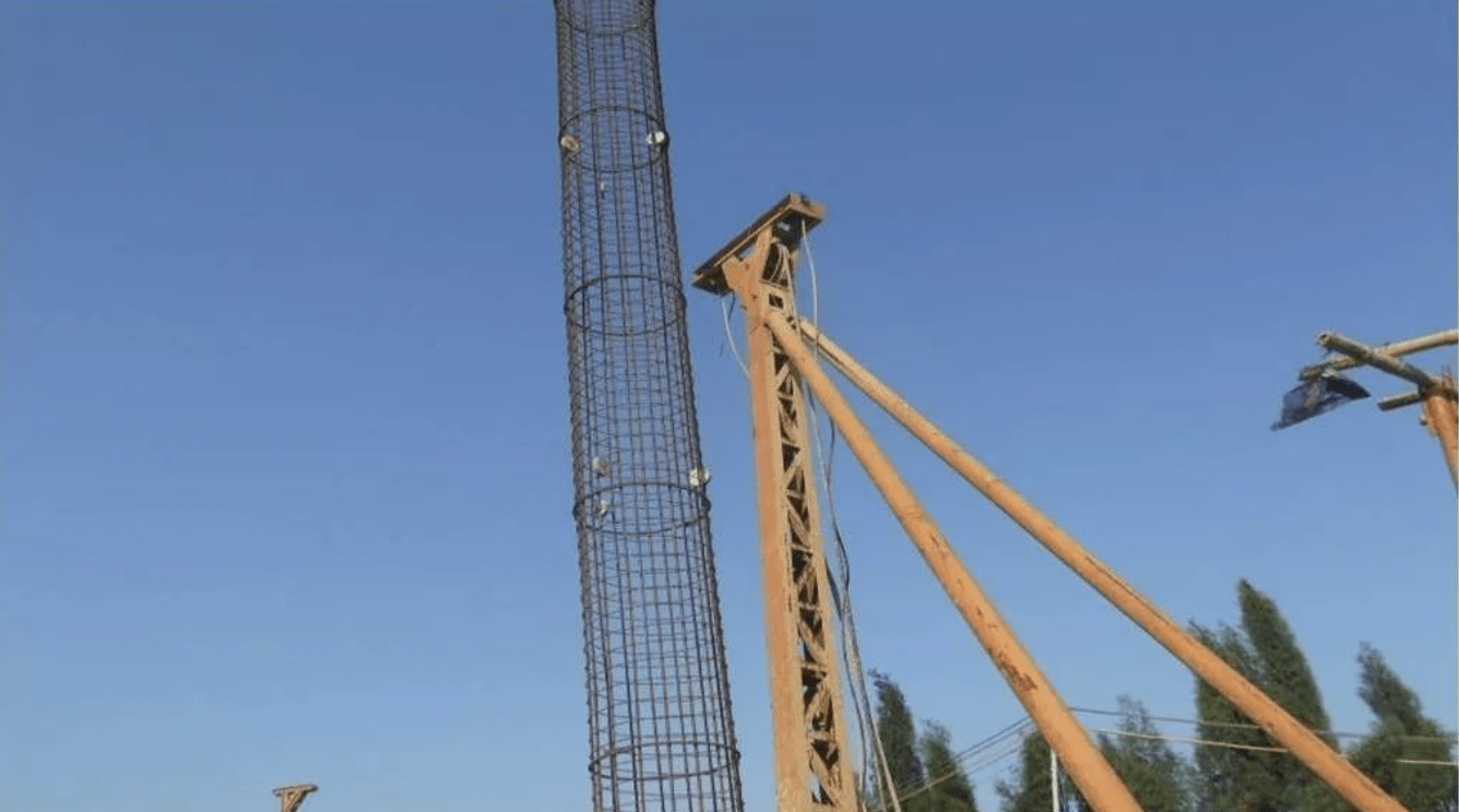
Bored cast-in-place piles have the advantages of low construction noise, and low vibration, pile length…

1 year ago

Common Quality Problems and Prevention Measures for Bored Pile Construction!

    Bored cast-in-place piles have the advantages of low construction noise, and low vibration,…

1 year ago

The Four Major Construction Techniques of Rotary Drilling Rigs Have Been Summarized for You!

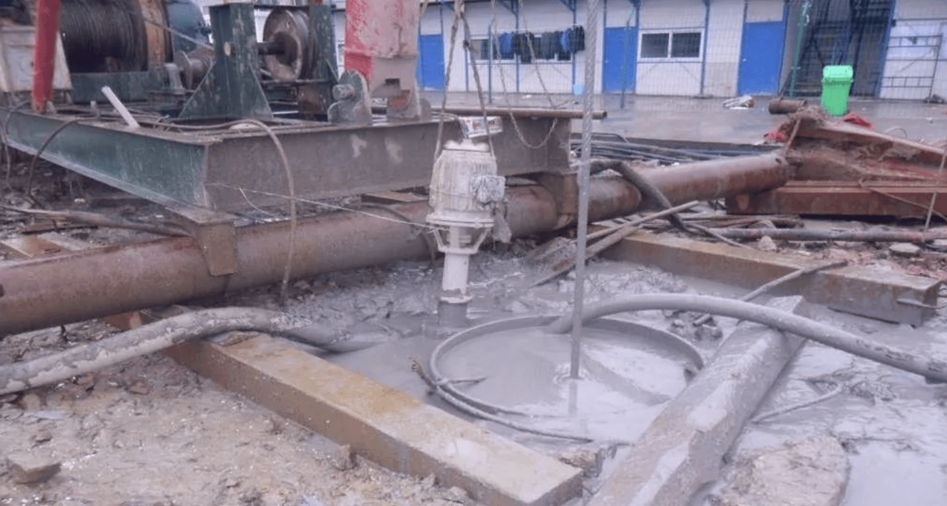
The four major construction technologies are dry hole forming technology, slurry static pressure technology, casing…

1 year ago

Read the Soil Nail Wall Construction Technology in One Article!

Soil nail support is a new type of retaining structure developed in recent years for…

1 year ago

Summary of the Key Points of the Entire Construction Process of Bored Piles!

Pile Foundation Classification and Construction Principles 1. Classification According to Load-Bearing Piles ① Friction type…

1 year ago

Steel Sheet Pile Cofferdam Construction Method

Steel sheet pile cofferdams are suitable for basic projects such as sandy soil, gravel soil,…

1 year ago