About large diameter piles (d≥800mm)
Size effect of extreme side resistance and end resistance.
1. Size effect of large-diameter pile tip resistance. The main reason is that the soil at the bottom of the hole rebounds due to unloading during pile hole formation, resulting in a reduction in end resistance, similar to the rebound of deep foundation pits. The static load test curves of large-diameter piles all show a slow deformation type, reflecting the progressive failure of their end resistance dominated by compressive shear deformation. G.G. Meyerhof (1998) pointed out that the ultimate end resistance of large-diameter piles in sandy soil decreases hyperbolically as the pile diameter increases.
2. The size effect coefficient of lateral resistance of large-diameter piles. After the pile is drilled, stress is released and the hole wall relaxes and deforms, resulting in a reduction in lateral resistance. The lateral resistance decreases in a hyperbolic manner as the pile diameter increases.
Pile foundation design principles in karst areas
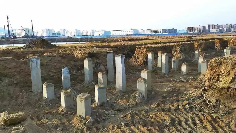
The reasons why pipe piles should not be used are as follows:
1. Once the pipe pile passes through the weathered rock layer, it immediately contacts the rock formation. The pipe pile is easily damaged, with a damage rate of 30% to 50%.
2. After the pile tip contacts the rock surface, it will easily slide along the inclined rock surface, causing the pile body to tilt, causing the pile body to break or the tilt rate to be too large.
3. The pile length is difficult to control and pile matching is difficult.
4. The pile tip falls on the bedrock, the surrounding soil has a small embedding force, and the pile body has poor stability.
Grouting After Pouring Piles
1. A certain period after the cast-in-place pile is built, cement slurry is injected through the grouting conduit preset in the pile body and the connected grouting valves at the pile end and pile side, so that the pile end and pile side soil (including sediment and mud) The skin) is reinforced, thereby increasing the bearing capacity of the single pile and reducing settlement. The bearing capacity can generally be increased by 40% to 100% (but the Hubei Provincial Standard DB42/242-2003 stipulates that it should not exceed 1.3 times that of similar non-grouted piles), and the settlement can be reduced by 20% to 30%. The cast-in-place piles can be used instead of sunken tube piles. All kinds of drilling, digging, and punching piles.
2. Reinforcement mechanism: The reinforcing effect of post-grouting on the pile side and pile end soil is as follows: solidification effect – the sediment at the bottom of the pile and the mud skin on the pile side is solidified due to the physical and chemical effects of slurry penetration, and the filling cementation effect – on the pile The bottom sediment and the mud skin on the side of the pile show filling and cementation due to penetration into the grouting, and the reinforcement effect is that network stones are formed due to splitting grouting.
3. Enhancement characteristics: The increase of end resistance is higher than that of side resistance, and the increase of coarse-grained soil is higher than that of fine-grained soil. Compound grouting at the pile end and pile side is higher than single grouting at the pile end and pile side. This is because the end resistance is sensitive to the influence of sediment. After post-grouting, the sediment is reinforced and the pile end has a bottom expansion effect. The reinforcement effect of the sediment and soil at the pile end is stronger than the reinforcement effect of the mud skin on the side of the pile; coarse-grained soil is a good material for penetration grouting. Grout and fine-grained soil are split grouting, and the reinforcing effect of the former is stronger than that of the latter.
4. Deformation characteristics after grouting: The Q-s curve of non-grouting is a steep drop type, while post-grouting is a slow deformation type, which improves the reliability of the pile and reduces settlement under the same safety factor. The main reasons for the decrease in settlement are as follows:
(1) The sediment and virtual soil at the bottom of the pile are solidified, and at the same time, the pile end has a bottom expansion effect.
(2) Due to the large grouting pressure (generally greater than 1MPa), the soil at the pile end is preloaded.
5. Things to note when designing:
(1) The grouting pipe should be connected by casing;
(2) When grouting pipes replace steel bars, it is best to embed additional steel bars at the top of the pile to avoid breaking the grouting pipe at the top of the pile due to improper construction protection;
(3) The grouting pipe should be fixed by binding.
Time Effect of Single Pile Bearing Capacity
The so-called time effect of single pile bearing capacity refers to the change of pile bearing capacity with time, which generally occurs in squeezed soil piles, especially prefabricated piles. Data from Shanghai shows that as the interval time after pile driving increases, the bearing capacity increases to varying degrees. After one year of interval, the pile bearing capacity can increase by 30% to 60%.
The reasons are analyzed as follows:
When the pile is driven, the soil is not easily compacted immediately (especially in soft soil). Under the strong squeezing force, a large pore water pressure is generated in the soil close to the pile body, and the structure of the soil also causes Failure and the shear strength is reduced (thixotropy). After a period of intermission, the pore water pressure gradually dissipates, and the soil gradually consolidates and becomes dense. At the same time, the structural strength of the soil gradually recovers, and the shear strength gradually increases. Therefore, the friction force and pile end resistance are also increasing.
The fastest improvement in strength occurs between 1 and 3 months. This is partly explained by the effects of high pore water pressures and displaced volumes, which produce rapid drainage consolidation of the soil adjacent to the piles. In fact, the soil close to the pile (in the range of about 50 to 200 mm) is often so consolidated that the effective diameter of the pile is increased.
The phenomenon of pile-bearing capacity increasing with time is more obvious in soft soil. However, the changing pattern in hard plastic soil needs further study.
Not all piles increase in capacity over time, and some piles decrease in capacity over time.
Explanation of Saddle-Shaped Distribution of Reaction Force on Pile Raft Foundation
According to the traditional load distribution principle, the load is distributed according to the stiffness. The low bearing capacity of the pile in the middle of the foundation indicates that the soil’s support stiffness for the pile is reduced, that is, the stiffness of the soil at the pile side and the end of the pile is reduced.
The reason is that the soil between the piles in the middle has to bear the load from the surrounding piles. Another way to explain it is that the limited soil between the piles in the middle cannot provide the required bearing capacity to the surrounding piles at the same time. In addition to relying on the soil on the inside of the foundation to provide bearing capacity, the piles near the outside can also use the soil near the outside of the foundation. Provides bearing capacity, while the soil near the outside of the foundation is less affected by the internal piles and can provide more bearing capacity than the soil inside. Therefore, the outside piles can bear more load than the internal piles, that is, the pile reaction force is in the shape of a saddle. type distribution.
In addition, the unloading of the soil between the piles during foundation pit excavation causes the soil between the piles to rebound, resulting in high pile stiffness near the edge of the foundation pit and low pile stiffness in the middle, which further aggravates the saddle-shaped distribution of foundation reaction forces.
The Overall Idea of the Design Principle of Changing Rigidity and Leveling
According to the superstructure layout, load, and geological characteristics, the interaction effect is taken into account, and a combination of strengthening and weakening, a combination of reducing settlement and increasing settlement, and overall leveling are adopted to minimize differential settlement, minimize internal forces of the foundation, and minimize resource consumption.
1. According to the building shape, structure, load, and geological conditions, select pile foundation, composite pile foundation, and rigid pile composite foundation, make a reasonable layout, and adjust the pile-soil support stiffness to match the load.
2. To reduce the weakening of the effective stiffness of the core area of the pile due to overlapping stress fields in each location, the layout of the pile-soil support body should be vertically misaligned or horizontally separated.
3. Considering the interaction effect of pile and soil, the adjustment of support stiffness should be controlled by the strengthening index. The strengthening index of the core area should be 1.05~1.30, and the weakening index of the outer frame area should be 0.95~0.85.
4. For buildings with main skirts, the design should be based on the principle of strengthening the main body and weakening the skirt.
5. The pile selection of the pile foundation and the determination of the pile end-bearing layer should be conducive to the application of post-grouting technology and should ensure a large adjustment space for the single pile-bearing capacity. Foundation piles should be concentrated under the column wall to reduce the internal force of the cap, maximize the load-sharing role of the foundation soil at the bottom of the cap, and reduce the interaction between the pile foundation under the column and the core pile foundation.
6. Based on the conceptual design, it is advisable to analyze the interaction between the superstructure-foundation-piles and soil and optimize the detailed design. The differential settlement should be stricter than the normative value to improve durability and reliability.
Pile Foundation Variable Stiffness Design Details
1. Frame and tube structure
The foundation piles of the core tube and outer frame columns should be arranged in groups under the core tube and columns to reduce the internal force of the cap and the adjacent influence of each part.
Based on the balance between the characteristic value of the total bearing capacity of the pile raft and the standard combination value of the total load effect, the core area is strengthened and the outer frame area is weakened. The strengthening index of the core area should be 1.05~1.15 when the pile end planes of the core area and the outer frame area are vertically misaligned or the number of piles under the columns in the outer frame area does not exceed 5. When the outer frame is a row of columns, the lower value should be used. When the columns are arranged in a row, the higher value is taken; when the pile end planes are at the same elevation and the number of piles under the column exceeds 5, the core area strengthening index should be 1.2~1.3, the lower value is taken when the columns are in the first row, and the high value is taken when the columns are in the second row.
The weakening index of the outer frame area is determined based on the relationship that the higher the strengthening index of the core area, the lower the weakening index of the outer frame area; or based on the balance between the total bearing capacity characteristic value and the total load standard value, the strengthening index of the core area is controlled separately to weaken the outer frame area. The index decreases accordingly.
Frame shear, frame-supported shear wall, and tube-in-tube structural forms are determined by referring to the frame-tube structure.
2. Shear wall structure
The shear wall structure has good structural integrity and the load distribution under the wall is relatively even. Therefore, piles should be reinforced in places with high load concentration such as elevator shafts and stairwells. Foundation piles should be arranged under the wall, and piles should be placed at intersections and corners of the wall. When the bearing capacity of a single pile is small and piles are placed throughout the hall, the interior should be strengthened and the periphery weakened.
3. Pile foundation cap design
For caps designed with variable rigidity, the cross-section and reinforcement, minimum plate thickness, and beam height should be determined according to the calculation results. For slab caps with beams under columns, the height-to-span ratio of the beams and the thickness-to-span ratio of the flat caps, It is advisable to take 1/8; the ratio of the plate thickness of the beam-slab raft cap to the short side clear span of the maximum two-way plate area should not be less than 1/16, and the thickness should not be less than 400mm; for the flat plate cap under the wall, the thickness-span ratio should not be Less than 1/20, and the thickness is not less than 400mm; the minimum reinforcement ratio of the raft should meet the requirements of the specification.
When selecting the type of raft cap, for the frame-tube structure, when the core tube and piles are arranged under the column, the core tube should be flat plate, and the outer frame area should be beam-plate type. For shear wall structure, a flat plate should be used. The cap reinforcement can be determined based on local bending moment calculations.
4. Joint action analysis and settlement calculation
For the frame-tube structure, joint interaction calculation and analysis should be carried out to determine the settlement distribution, pile-soil reaction force distribution, and cap internal force. When joint action analysis is not performed, settlement should be calculated according to specifications, and indicators such as differential settlement should be tested accordingly.
Basic Laws of Stress on Pile Foundations
As the vertical load increases, the side resistance occurs before the end resistance. As the deformation increases, end resistance comes into play. Generally, when the relative displacement of pile and soil reaches about 4~10mm (depending on the type of soil), the lateral resistance can be fully exerted, while the full exertion of end resistance requires the relative displacement of pile and soil to reach d/12~d/4 (small diameter pile). d is the pile diameter, d/4 for clay soil, and d/12~d/10 for sandy soil.
Characteristics of Pile Foundation Settlement
1. Temporality. The settlement of pile foundations in soil takes a long time. In the Shanghai area, it is generally 5 to 7 years after completion for the settlement rate to drop below 4mm per year. The main part of the settlement of pile foundations in soft soil is related to the time factor. According to the current understanding of soil mechanics, the main part of the settlement is composed of consolidation deformation and soil rheology.
2. Penetration deformation. The explanation for the penetration deformation is as follows: During the gradual loading process on the pile top of the pile group, when the load on the top of the single pile is small, the upper pile body of the pile is first compressed, and the upper mass point of the pile is displaced downward between the soil masses, resulting in Relative displacement, the friction force is generated when the soil prevents the displacement of the upper part of the pile. The pile top load gradually spreads into the soil through friction. It not only spreads into the soil between the piles but also spreads into the soil below the pile tips. At this stage, the distribution of pile side resistance may be larger at the upper end of the pile and smaller at the lower end, gradually developing downward.
The stress in the soil is mainly transmitted to the upper soil due to the frictional force on the upper part of the pile, so the stress in the soil between the piles is also greater than the stress in the soil below the pile tip. As the loading continues, the slip area on the upper part of the pile side continues to expand downward. The pile tip bearing capacity begins to take effect, and the stress in the soil below the pile tip will increase more than the stress in the soil between the piles. (It is generally accepted that when the relative displacement reaches 2~5mm, the pile side friction reaches the limit, and relative slippage between piles and soil will occur.) After the loading is completed, the soil between the piles and the soil at the pile tip will be consolidated under the action of the stress field. and rheology will continue to deform. Among them, the consolidation compression and flow of the soil between the piles are more important. Since the deformation of the pile body is the elastic compression of the material, during this period, the downward displacement of the soil particles between the piles is greater than that at the same cross-sectional depth. The displacement of the pile mass point, that is, in the upper part of the pile, the difference in displacement between the downward displacement of the pile body mass point and the adjacent soil mass point will decrease, or even change direction. The friction caused by the displacement difference will also be reduced, and even negative friction will be generated.
To balance the reduced soil reaction force around the pile with the pile top load, a new settlement increment must be generated to increase the relative displacement of the pile and soil to increase the soil reaction force. In this project, new slips (penetration deformation) will occur. The general trend is to gradually reduce the frictional resistance in the upper part of the pile, and gradually increase the frictional resistance and pile end support force in the lower part of the pile. When there are a large number of piles, the piles are arranged densely, and the stress in the soil between the piles is large, negative friction may occur on the upper part of the piles, and the soil under the cap will be separated from the bottom surface of the cap.
3. The settlement of the friction pile foundation in the soil is caused by the compression of the pile body, the penetration deformation of the pile tip, and the compression deformation (consolidation and rheology) of the soil under the pile tip.
Piles and Soil Work Together
The joint work of pile and soil is a typical nonlinear process. Experiments on pile-soil working together show that:
1. In the loading process in which piles and soil act together, piles and soil act sequentially, which is a nonlinear process. The pile always plays a supporting role first. After the bearing capacity of the pile reaches 100%, the soil can play a supporting role only after reaching the limit. The pile-soil sharing ratio changes with the loading process and there is no fixed sharing ratio.
2. When the pile top load is less than the ultimate load of a single pile, the increased load at each level is mainly borne by the pile, and the pile bears about 90~95%.
3. After the load on the pile reaches the yield load of a single pile, the load borne by the foundation soil at the bottom of the cap platform increases significantly, the load-sharing ratio of the pile significantly decreases, and the settlement velocity also increases.
4. The ultimate bearing capacity of the pile-soil interaction > the bearing capacity of a single pile + the ultimate bearing capacity of the foundation soil.
Thank You!
Bored cast-in-place piles have the advantages of low construction noise, and low vibration, pile length…
Bored cast-in-place piles have the advantages of low construction noise, and low vibration,…
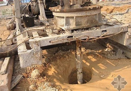
The four major construction technologies are dry hole forming technology, slurry static pressure technology, casing…
Soil nail support is a new type of retaining structure developed in recent years for…
Pile Foundation Classification and Construction Principles 1. Classification According to Load-Bearing Piles ① Friction type…
Steel sheet pile cofferdams are suitable for basic projects such as sandy soil, gravel soil,…