Spiral drilling, positive circulation rotary drilling, reverse circulation rotary drilling, submersible drilling, punching drilling, impact drilling, and bucket drilling.
The drilling site should be cleared of debris, soft soil replaced, leveled, and compacted. When the site is located in shallow water, steep slopes, or mud, an island can be built, or a work platform can be set up with sleepers or steel. When located in deep water, temporary piles can be driven to set up a fixed work platform, a steel casing guide frame can be assembled on the drilling platform, and a lifting device can be used to drive the steel casing into the water. The work platform must be strong and stable, able to withstand all static and live loads during construction operations, and the safe entry and exit of construction equipment should also be considered.
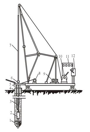
Fix the position of the pile hole, protect the hole mouth, and prevent groundwater from flowing in; Increase the water pressure in the hole to prevent the hole from collapsing, and guide the direction of the drill bit when drilling.
Requirements for making casing: Casings are usually made of reinforced concrete and steel, depending on the specific situation. The thickness of the steel casing is 4~8mm, and the thickness of the reinforced concrete casing is 8~10cm.
There are 1~2 overflow holes on the top of the casing; the inner diameter of the casing is slightly larger than the design diameter of the bored pile.
The diameter of the hole drilled by a rotary drill should be increased by 20~30 cm; the diameter of the hole drilled by an impact drill and a punching drill should be increased by 30~40 cm.
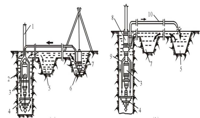
Requirements for burying casing: Before drilling, lay out the lines and locate the position on site, remove the surface soil of the pile hole according to the pile position, and bury the casing; the casing can be buried by digging or hammering, vibrating, pressurizing and other methods; the burial depth is generally 2-4 meters, and should be deepened in special cases; the elevation of the top of the casing should meet the requirements for the water level setting height in the hole.
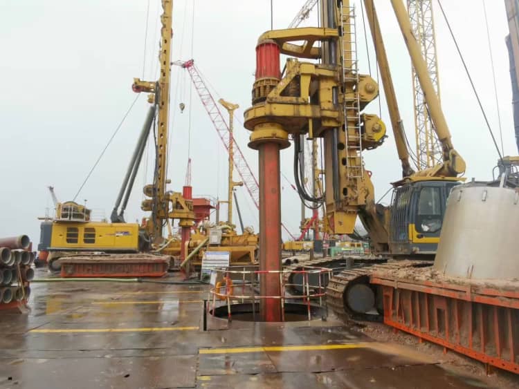
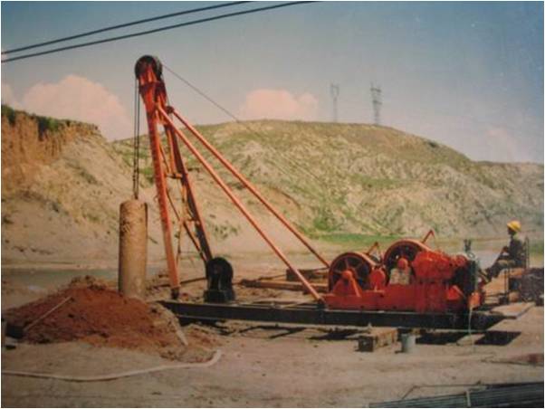
Assemble the steel casing guide frame on the drilling platform, measure and lay out the pile position → dock the steel casing → hoist the steel casing into the water → adjust the inclination and position of the casing and slowly enter the bed until it is stable → install the vibration pile hammer to vibrate and sink → install the drilling rig to start the construction of bored piles on the water. During the vibration sinking process of the steel casing, accurate positioning, tracking, monitoring, and adjustment must be carried out to meet the requirements of the specifications to ensure the smooth progress of the bored pile construction. The steel casing is rolled with Q235 steel plates with a thickness of 4 to 12 mm. The inner diameter of the casing should be 20-40 cm larger than the pile diameter. The steel casing is manufactured in sections in the workshop and sinks as a whole after docking on the platform. During the sinking, wooden wedges are used to adjust the deviation between the guide frame and the casing at any time. The bottom of the casing is required to reach the top of the pebble layer. The top of the casing should be 1.0-2.0 m higher than the construction water level or groundwater level.
An island should be built before the pile construction on the river beach. The height of the island should be 0.5m above the construction ground, and the height of the casing should be 0.3m above the ground. When there is pressurized water in the borehole, it should be at least 2.0m above the stabilized pressurized water level. The steel casing is made of a Q235 steel plate with a thickness of 4-12mm, and the inner diameter should be 20-40cm larger than the pile diameter. The buried depth of the casing meets the following requirements: not less than 1m for clay soil and not less than 2m for sandy soil. When the surface soil is soft, the casing should be buried at least 0.5m into the harder and denser soil layer. The casing is buried on the beach, and clay is backfilled around the casing and compacted in layers; the deviation between the center of the top surface of the casing and the designed pile position should not exceed 5cm, and the inclination should not exceed 1%. When building an island in water, the casing should be buried 1m below the riverbed surface.
In bored pile construction, the role of mud is to increase the static pressure on the hole wall and form a layer of mud skin on the hole wall to block the aquifer and protect the hole wall from collapse. Drilling mud is generally made of water, clay (bentonite), and additives in an appropriate mix ratio. The colloid rate of good mud is not less than 95%, and the sand content is not more than 4%. Before pile foundation construction, a mud pool should be excavated, and good slurry clay or bentonite should be selected and prepared. The slurry volume is twice the concrete volume of the pile. The mud specific gravity can be adjusted in time according to the different strata drilled.
(1) General requirements:
Before the drilling rig is in place, check all preparations for drilling. The base and top of the drilling rig should be stable after installation, and no displacement or sinking should occur during drilling, otherwise, it should be handled in time. Drilling operations should be carried out continuously in shifts, and drilling construction records should be filled in. When handing over shifts, the drilling situation and precautions for the next shift should be explained. Attention should be paid to geological changes. Slag samples should be collected at the places where the strata change, and recorded in the record book after identification and compared with the design geological data.
(2) Drilling:
① Positive circulation drilling construction:
Positive circulation is to use a mud pump to pass mud through the top of the hollow drill pipe at a certain pressure and spray it out from the bottom of the drill pipe. The drill cone at the bottom will loosen the soil and become drilling slag when rotating. It is suspended by the mud and overflows with the mud to the mud tank outside the hole. It is precipitated and purified in the sedimentation tank and then recycled. Characteristics of positive circulation drilling: simple equipment, easy operation, mature technology, and high drilling efficiency when the hole depth is not too deep and the hole diameter is less than 800mm. When the pile diameter is large, the annular section between the drill rod and the hole wall is large, the reflux velocity is low during mud circulation, and the mucking capacity is weak. If the mud reflux velocity is increased to 0.20m/s~0.35m/s, the displacement of the mud pump needs to be very large, which is sometimes difficult to achieve. At this time, the relative density and viscosity of the mud have to be increased. However, if the relative density of the mud is too large and the viscosity is large, it is difficult to discharge the drilled mud, and the thickness of the mud skin on the hole wall is large, which affects pile formation and hole cleaning.
② Reverse circulation drilling construction:
The circulation method of the mud of the reverse circulation drilling rig is just the opposite. The mud flows from the outside of the hole into the hole, and the drilled mud is sucked out from the top of the drill rod through the center of the drill rod by a vacuum pump or other methods (such as air mud suction machine, etc.), or the suction pump is drilled together with the drill bit to suck the drilled mud out of the hole from the bottom of the hole. Characteristics of reverse circulation drilling: Mud flows into the borehole from the annular gap between the drill pipe and the hole wall to cool the drill bit and carry the slag back to the ground from the inner cavity of the drill pipe. Since the cross-sectional area of the inner cavity of the drill pipe is much smaller than the annular cross-sectional area between the drill pipe and the hole wall, the return speed of the mud is large, generally up to 2 m/s ~ 3 m/s, which is dozens of times the return speed of the mud in the positive circulation process. Therefore, it can improve the slag discharge capacity, keep the hole clean, reduce the chance of repeated crushing of drilled slag at the bottom of the hole, and greatly improve the drilling efficiency. This drilling process is an effective and advanced drilling process for large-diameter drilling construction, so it is widely used.
③ Impact drilling:
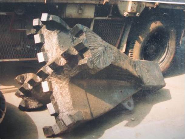
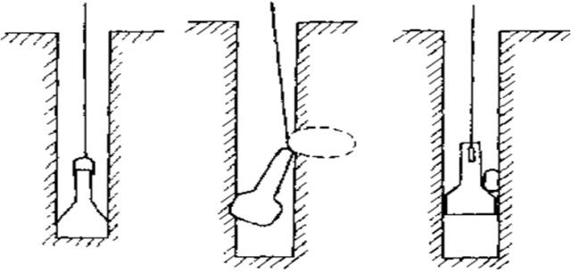
The impact drill machine raises the heavy drill bit (impact hammer) with blades to a certain height through the frame and winch, and cuts and breaks the rock layer or impacts the soil layer to form a hole by the impact force of free fall. The impact drill bit has the shape of a cross, I-shaped, herringbone, etc., and the cross-shaped impact drill bit is generally used. Before punching, the steel casing should be buried, and the wall protection material should be prepared. The impact drill is mainly used to make holes in the rock layer. When making holes, the impact cone drill bit is lifted to a certain heigh,t and the rock layer is broken by the impact force of free fall, and then the slag slurry in the hole is removed with a slag barrel.
④ Drilling bucket drilling (rotary drilling)
There are three main drilling processes: dry drilling, water hole drilling, and mud wall drilling. l Its main features are easy movement with self-contained crawlers, fast hole-making speed, and a clean hole bottom. It is mainly suitable for construction in sandy soil, clay soil, silty soil, and other soil layers. The maximum hole diameter can reach 1.5~4m, and the maximum hole depth is 60~90m, which can meet the requirements of various large-scale foundation construction.
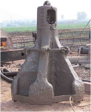
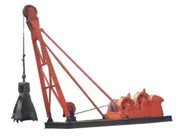
⑤ Features of full-casing punching and grabbing:
No noise, no vibration; no mud is used; soil and lithology characteristics can be intuitively judged during excavation, and for end-bearing piles, it is easy to determine the pile length on site; fast excavation speed and large excavation depth; easy to grasp the verticality of the hole; the hole wall will not collapse, and the hole quality is high. High pile quality, standard hole diameter, and small filling coefficient; thorough hole cleaning and fast speed; self-propelled, easy to move on site. The punching and grabbing cone has a heavy iron block and a movable grab piece on the cone head. The punching and grabbing cone is lifted to a certain height by the frame and winch. When falling, the drum brake is released, the grab piece opens, and the cone head falls freely into the soil, and then the winch is started to lift the cone head. At this time, the grab piece closes and grabs the soil. The punching and grabbing cone is lifted to the ground as a whole to unload the soil residue, and the hole is formed in a cycle. The punching and grabbing cone hole construction process, casing installation requirements, mud wall protection cycle, etc., are the same as the impact hole construction. It is suitable for punching holes in soft soil layers (sand, clay), but when encountering hard soil layers, it is advisable to use an impact drill for construction.
⑥ Submersible drilling rig drilling
A submersible drilling rig is a rotary drilling machine whose waterproof motor speed change mechanism and drill bit are sealed together. After being positioned by the pile frame and drill rod, it can be submerged in water and mud to drill holes. After the mud is injected, the cut soil particles and stone slag in the hole are discharged to the outside of the hole through the positive circulation or reverse circulation slag discharge method. A submersible drilling rig is a special drilling machine that combines the motor, speed change mechanism, and bottom drill bit into a sealed one. This machine is small in size, light in weight, and easy to carry. The pile frame is light and flexible to move. The drilling speed is fast (0.3~2.0m/min), and the drilling rig has low noise and high drilling efficiency. The maximum hole diameter is 0.8-2m, and the drilling depth is 50m.
⑦ Hole drilling with a full-leaf auger
The hole diameter is 400-600mm, and the depth is 8-12m. It is suitable for general clay soil, sandy soil, and artificial fill foundations above the groundwater level. It is not suitable for drilling operations in soil layers below the groundwater level andin silty soil.
Regardless of the drilling method, the hole position must be accurate, and the hole should be drilled slowly when drilling. Drilling can only be accelerated after the guide part or the drill bit has completely entered the formation. Both positive and reverse circulation drilling (including submersible drilling) should adopt decompression drilling, that is, the main hook of the drilling rig must always bear part of the gravity of the drilling tools, and the drilling rig at the bottom of the hole does not exceed 80% of the sum of the gravity of the drilling tools (minus buoyancy). When drilling with the full casing method, to install the drilling rig flat, the first section of the casing pressed in must be vertical. After the start of drilling, the horizontal position and vertical line of the casing should be checked at any time. If deviation is found, the casing should be pulled out, adjusted, and pressed in again for drilling.
When drilling and removing slag, lifting the drill bit to remove soil, or stopping drilling for some reason, the specified water level and the required relative density and viscosity of the mud should be maintained in the hole. When dealing with accidents in the hole and stopping drilling, the drill bit must be pulled out of the hole. Every 2m of drilling or when the stratum changes, the drill cuttings sample should be collected from the mud tank, the soil quality should be identified and recorded, the drill cuttings should be removed in time, and the mud should be replaced, so that the drill bit can drill into fresh stratum frequently. At the same time, pay attention to the changes in the soil layer. Slag samples should be collected at the places where the rock and soil layers change, the soil layers should be identified and recorded in the record table for verification with the geological profile.
(3) Hole cleaning When the borehole reaches the design elevation, the hole should be cleaned in time to reduce the thickness of the sediment at the bottom of the hole and ensure the bearing capacity of the pile foundation; replace the mud in the hole, reduce the mud specific gravity and sand content, and ensure the quality of concrete pouring. Hole cleaning methods include slurry replacement, slurry extraction, slag removal, air compressor injection, mortar replacement, etc., which can be selected according to the specific situation.
After the hole inspection is qualified, the hole should be cleaned immediately. The hole-cleaning method should be determined according to the hole-forming process, mechanical equipment, and engineering geological conditions. There are mainly mud suction methods, prize exchange methods, slag removal methods, etc. If there is no design requirement before pouring underwater concrete, the thickness of the friction pile sediment should be less than 30 cm, and the rock-embedded pile should be less than 10 cm; the mud index after hole cleaning should meet the following standards: there are no 2~3mm particles in the mud hand model discharged or extracted from the hole, and the mud specific gravity is not more than 1.1; the sand content is less than 2%; the viscosity is 17-20s. Attention should be paid to hole cleaning: it is strictly forbidden to use the method of increasing the hole depth instead of hole cleaning (rotary drilling rigs must be equipped with hole cleaning equipment). Before pouring concrete, the on-site supervisor should be notified to check the sediment thickness. Only when the requirements are met can the pouring be carried out.
(4) Drilling quality inspection. After drilling, the hole should be inspected, and the inspection content should include the hole center, hole depth, hole diameter, inclination, etc.
The design support personnel should be notified to conduct on-site geological confirmation.
Drilling inspection items and allowable deviations: hole diameter and hole depth should meet the design requirements; the allowable deviation of the hole center is 100mm, and the inclination is 1%.
Note for drilling quality inspection: When inspecting the hole, the on-site supervisor should be notified as soon as the hole is drilled for acceptance.
At this time, the requirements for the production of the borehole detector: it must have sufficient rigidity, and the outer diameter must be the same as the designed pile diameter; the length of the borehole detector should be 4-5 times the designed pile diameter, and should not be less than 6 meters; the two ends of the borehole detector should be tapered, and the height should not be less than the radius of the borehole detector.
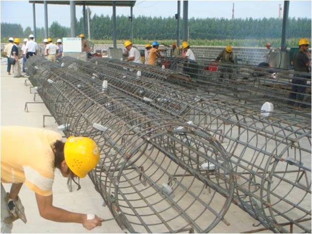
Steel Cage Processing: Steel cages are manufactured in sections in the steel processing workshop or on-site, preferably with fixed steel length. The main bars must be straightened before manufacturing, without local bending. The main bars should generally be made of whole steel bars as much as possible. The steel bar joints after segmentation should be staggered to ensure that the number of joints in the same section does not exceed 50% of the total number of main bars, and the staggered spacing of the joints is not less than 35d (d is the diameter of the steel bar), and shall not be less than 50cm.
The welding and binding of the steel cage must be firm, and the length and fullness of the weld should be guaranteed. After the pile body steel cage is manufactured in sections, it is hoisted to the site and connected while being lowered. When manufacturing in sections, lap welding is used. The ends of the two steel bars should be folded to one side in advance to make the axes of the two jointed steel bars consistent. The length of the joint is not less than 10d for single-sided welding and not less than 5d for double-sided welding. The weld requires the removal of welding slag and fullness of the weld.
Lifting and installation of the steel cage:
To ensure that the skeleton does not deform during lifting, it is advisable to use two-point lifting. The first lifting point is set at the lower part of the skeleton, and the second lifting point is set between the midpoint and the upper third of the skeleton length. When lifting, first lift the first lifting point to lift the skeleton slightly, and then lift it at the same time as the second lifting point. After the skeleton leaves the ground, stop lifting the first lifting point and continue to lift the second lifting point. As the second point continues to rise, slowly relax the first lifting point until the skeleton is perpendicular to the ground and stops lifting. When the skeleton enters the hole, it should be straightened and slowly lowered. It is strictly forbidden to swing and collide with the whole wall.
The top of the steel cage should be set with lifting bars according to the hole’s top elevation. When the steel cage is extended, the two steel cages must be kept vertical and well aligned. When lifting the steel cage, align it with the hole position and place it gently and slowly. If there is an obstacle, lift and lower it gently and rotate it forward and backward to lower it. Do not lift it and drop it suddenly, or force it down to prevent it from damaging the whole wall and causing the hole to collapse. During the lowering process, always pay attention to the water level in the hole. If any abnormality is found, stop immediately and check whether the hole has collapsed.
The conduit should be assembled and numbered before use. The length and number of sections of the conduit should be calculated according to the hole depth. The conduit should be straight, and a watertight test should be carried out. Confirm that the conduit is leak-proof and the disassembly is in good condition before it can be lowered into the hole. Be careful when lowering the conduit to avoid hanging and hitting the steel cage, and keep records. After the second hole cleaning is completed, the conduit is gently lowered to the bottom and then lifted 25 to 40 cm, and compared with the theoretical length of the conduit. After matching, the conduit is fixed on the hole seat of the pouring platform.
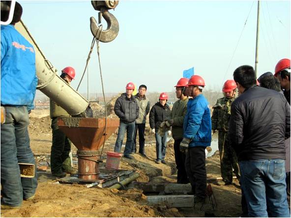
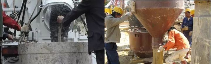
Pouring underwater concrete: Calculate and control the amount of the first batch of bottom-sealing concrete. There is a certain impact energy when falling, which can discharge the mud from the conduit and bury the lower end of the conduit into the concrete 1 m- 3 m deep. When the pile body is long, the depth of the conduit buried in the concrete can be appropriately enlarged. Sufficient impact energy can flush the sediment at the bottom of the pile as much as possible, which is an important link to control the sediment at the bottom of the pile and reduce post-construction settlement. The pile foundation concrete is transported by tank trucks and poured through conduits. The diameter of the conduit is 25 to 30 cm. During the pouring process, the buried depth of the conduit should be controlled within 2 to 6 m.
At the same time, the position of the concrete surface in the hole should be frequently measured, and the buried depth of the conduit should be adjusted immediately. After the pouring starts, it should be carried out compactly and continuously without stopping in the middle. During the pouring process, the concrete mixture should be prevented from overflowing from the top of the funnel or falling from the outside of the funnel into the bottom of the hole, so that the mud contains cement and becomes thick and condensed, resulting in inaccurate measurement. During the pouring process, attention should be paid to observing the drop of concrete in the pipe and the rise and fall of the water level in the hole, timely measuring the height of the concrete surface in the hole, and correctly directing the lifting and removal of the conduit. When lifting the conduit, the axis should be kept vertical and the position should be centered, and it should be lifted gradually.
If the conduit flange is stuck on the steel frame, the conduit can be rotated to disengage the steel frame and then moved to the center of the drill hole. To ensure the quality of the pile top, 0.5m to 1.0m should be poured above the design elevation of the pile top.
(1) Hole collapse accidents may occur in various drilling methods. Hole collapse is characterized by a sudden drop in the water level in the hole.
Fine blisters appear at the orifices;
The amount of slag produced increases significantly without any footage or very little footage; the hole depth suddenly becomes shallower and the drill bit cannot reach the original hole depth; the load of the drilling rig increases significantly, etc. Reasons for hole collapse: The relative density of the mud is insufficient, and other mud performance indicators do not meet the requirements, so that the hole wall does not form a solid mud skin. The water head in the hole is not high enough because the mud (or water) is not replenished in time after the slag is discharged, or the river water or tide rises, or the pressure water appears in the hole, or the hole passes through a highly permeable layer such as gravel, and the water in the hole is lost. If the casing is buried too shallowly, the lower hole will leak or collapse, or the ground near the hole will be soaked with water and become soft, or the drilling rig will be in direct contact with the casing, causing the hole to collapse due to vibration and expand into a larger collapse hole.
Drilling too fast in soft sand. When the drill cone is proposed for drilling, the rotation speed is too fast, and the idling time is too long. The water head is too high, causing slurry to seep into the hole wall or reverse perforation at the bottom of the casing. The water level in the hole is lower than the groundwater level. Improper hole operation, the water supply nozzle directly washes the hole wall, the hole cleaning time is too long, or the hole cleaning pause time is too long. Collision with the hollow wall when hoisting into the steel frame. Prevention and treatment of hole collapse: When drilling in loose silt soil or quicksand, the footage speed should be controlled, and high-quality mud with a larger relative density, viscosity, and colloid ratio should be used, or clay and gravel should be put in to make the clay paste, debris, etc. are squeezed into the hole wall. When a hole collapse occurs, the casing can be removed immediately and the drilled hole can be backfilled, the casing can be re-buried and then drilled, or the steel casing can be lowered to at least 1m below the uncollapsed location.
If collapse occurs in the hole, if it is not serious, you can increase the proportion of mud and continue drilling. If it is more serious, you should identify the collapse location and backfill a mixture of sand and clay soil (or gravel and loess) to 1m-2m above the collapsed hole, or even all should be backfilled before drilling. Before drilling, the backfill should be deposited and compacted. When cleaning the hole, a special person should be designated to add grout (or water) to ensure the necessary water head height in the hole. It is best not to insert the water supply pipe directly into the drill hole. The water should be slowed down through a sink or pool and then flow into the drill hole to avoid scouring the hole wall. The suction machine should be straightened to prevent it from touching the hollow wall. It is not advisable to use excessive wind pressure, and it should not exceed 1.5-1.6 times the water column pressure in the borehole. When hoisting it into the steel frame, insert it vertically into the center of the hole to avoid touching the hole wall.
(2) Causes of borehole deflection: encountering large boulders or probe rocks in the borehole; drilling at an angle on the rock surface at the junction of inclined soft and hard strata; or sand and pebble layers with widely different particle sizes. When drilling in the middle, the force on the drill bit is uneven; when the hole is enlarged, the drill bit swings to one side. The base of the drilling rig is not placed levelly or produces uneven subsidence and displacement; the drill pipe is bent, and the joints are incorrect. Prevention and treatment: When installing the drilling rig, the turntable and base should be level, and the lifting pulley rim, the stuck hole for fixing the drill pipe, and the center of the casing should be in a vertical line. and check and correct frequently. Since the active drill pipe is long, the upper part swings too much when rotating. It is necessary to add a guide frame to the drill frame and control the lifting faucet on the rod to drill centered along the guide frame. The drill pipe joints should be inspected one by one and adjusted in time. When the active drill pipe is bent, use a jack to straighten it in time.
(3) Causes of falling objects from the drill: strong lifting and twisting when the drill is stuck, improper operation, overloading, or fatigue fracture of the drill pipe or wire rope. The drill pipe joint is defective or slippery. The motor wiring was incorrect, the drill rig rotated in the opposite direction, and the drill pipe became loose. The welding parts, such as the steering ring and steering sleeve, are disconnected. Wrenches, crowbars, etc, may fall into the machine due to careless operation. Preventive measures: Before drilling, the falling objects in the hole should be removed. Sporadic iron parts can be picked up by electromagnets. Larger falling objects and drilling tools can also be salvaged with a punching cone, and then the casing mouth should be capped. Frequently inspect drilling tools, drill pipes, wire ropes, and couplings. Treatment method: After the drill is dropped, the situation should be investigated promptly. If the drill cone is buried by sediment or collapsed hole soil and rocks, the hole should be cleaned first so that the salvage tool can contact the drill pipe and drill cone.
(4) Paste drilling and buried drilling Paste drilling and buried drilling often occur in forward and reverse circulation rotary drilling. The characteristic of paste drilling is that the footage is slow when drilling in fine-grained soil layers, or even the pump is blocked when drilling in fine-grained soil layers. Prevention and treatment methods: For forward and reverse circulation rotary drills, mud bags can be removed, the relative density and viscosity of the mud can be adjusted, the pump volume should be increased appropriately and an appropriate amount of sand and gravel can be put into the hole to solve the problem of mud bags and smudged drills. Use scrapers with small teeth and A drill cone with a large slurry outlet; if the drill is seriously stuck, the drill should be stopped and the drilling slag should be removed. Check and calculate the inner diameter of the drill pipe, the dimensions of the drilling slag inlet and outlet, and the slag discharge equipment.
(5) Hole expansion and shrinkage. Hole expansion is the result of hole wall collapse, which may occur in various drilling methods. If the hole is expanded due to local collapse in the hole, and the hole can still reach the designed depth, no treatment is required. However, the amount of concrete poured is greatly increased. If the hole continues to collapse after expansion and affects drilling, it should be treated as a hole collapse accident. There are two reasons for shrinkage cavities: one is that the drill cone is not repaired in time, and the severely worn drill cone often drills holes that are slightly smaller than the designed pile diameter; the other is that there is soft plastic soil in the ground, commonly known as rubber soil. When exposed to water, the hole diameter shrinks. To prevent shrinkage holes, the former should repair the worn drill bit immediately, while the latter should use high-quality mud with a small water loss rate to protect the wall, rotate it quickly and slowly, and rotate it two or three times, or use a winch to hoist it. The drill hammers up and down and sweeps the hole left and right repeatedly to expand the hole diameter until the shrinkage hole reaches the designed hole diameter.
(6) Plum blossom holes (or cross holes) often occur when drilling with an impact cone. The punched holes are not round and have the shape shown in the figure. They are called plum blossom holes or cross holes.
The steering device at the top of the cone failed, so that the cone did not rotate and always impacted up and down in one direction. The relative density and viscosity of the mud are too high, and the impact and rotation resistance are too great, making it difficult for the drill bit to rotate. During operation, the wire rope is too loose or the stroke is too small, the punch cone is dropped as soon as it is lifted, the drill bit does not rotate for enough time, or the rotation is very small, and the impact position cannot be changed. If there are non-homogeneous layers, such as the drift pebble layer, accumulation layer, etc., probe stones are likely to appear, causing local hole walls to protrude and the holes to be out of round. Preventive measures: The flexibility of the steering device should be checked frequently, and the malfunctioning steering device should be repaired or replaced in time. Select mud with appropriate viscosity and relative density, and dig out the slag promptly. When using a low stroke, use a higher stroke for each impact section to modify the hole shape alternately. After a plum blossom hole appears, the drilled hole can be backfilled with clay mixed with tablets and pebbles, and then filled again.
(7) Cone stuck: It often occurs when drilling with an impact cone. The reason is that the drilled hole forms a plum blossom shape, and the punch cone is stuck in a narrow part. If the punch cone is not repaired by welding in time, the diameter of the hole gradually becomes smaller. After welding and repair, the punching cone becomes larger, and if it is hit hard with a high stroke, it is easy to cause the taper to get stuck.
The small probe stone that extends into the hole has not been broken and stuck on the cone foot or top.
Stones or other objects fell from the orifice, blocking the punch cone. The impact stroke in the clay layer was too high and the mud was too thick, causing the punching cone to be sucked. The big rope was loosened too much, and the punch cone tipped over and pressed against the wall.
When the drill is stuck in the plum blossom, if there is room for the cone head to move downward, the drill bit can be moved downward and rotated in the direction of the larger diameter to lift the drill bit. You can also loosen the wire rope to rotate the drill cone to an angle, which may pull the drill cone out. The stuck drill should not be lifted forcefully to prevent the hole from collapsing or burying the drill.
It is advisable to use the method of bumping from bottom to top, lightly hitting the stone at the stuck point, sometimes making the drill head move up and down, and also can get out of the stuck point or make the fallen stone fall. Put a thicker wire rope with a salvage hook or salvage rope into the hole, hook the punch cone back, and lift it at the same time as the big rope, or lift it alternately, and swing it up and down, left and right several times to test, sometimes the punch cone can be pulled out. During the salvage process, continue to stir the mud to prevent sedimentation and burying the drill. Use other tools, such as small punch cones, small slag barrels, etc., to impact the hole, squeeze the stones of the stuck cone into the hole wall, or move the punch cone away from the stuck point, and then pull the punch cone out. But keep the big rope steady to prevent the punch cone from falling suddenly.
Use compressed air or a high-pressure water pipe to go into the hole, aim at one side of the stuck cone or the suction cone, and shoot appropriately for a while to loosen the stuck point and then force it out. Use specially processed tools to adjust the drill bit against the hole wall. If the above methods are ineffective in lifting the cone, you can try the underwater blasting method. Put waterproof explosives (less than 1kg) in the hole, lower them to the bottom of the cone along the cone slide, and then detonate them to loosen the stuck cone. Then use a winch and a chain pulley to pull it out at the same time. Generally, it can be pulled out.
(8) External rod breakage: common in rotary drilling rigs. The cause of breakage: The drill rod used for small-diameter drilling in hydrogeology or geological drilling is used as large-diameter bored piles for bridges. Its strength and rigidity are too small, and it is easy to break. The speed selected during drilling is inappropriate, which increases the torsion or bending stress on the drill rod, resulting in breakage.
The drill rod has been used for too long, and the joints are damaged or the joints are worn too much. The geology is hard, and the penetration is too fast, causing the drill rod to work overloaded. Foreign objects appear in the hole, which suddenly increases the resistance without stopping the drilling in time. Prevention and treatment: Do not use drill pipes with severe bending. The connection threads of each section of the drill pipe and the connection between the drill pipe and the drill bit must be intact. The drill pipe joints connected by screw sleeves must have locking facilities to prevent reversal and loosening. The penetration speed should be controlled during drilling.
When encountering hard and complex geology, careful operation should be carried out. During drilling, the wear of each part of the drill tool and the strength of the joints should be checked frequently. If they do not meet the requirements, they should be replaced in time. If foreign objects are encountered during drilling, they must be handled before drilling. If a drill pipe breakage accident has occurred, the fallen drill pipe can be salvaged according to the above-mentioned salvage method. Check the cause and replace it with a new or larger drill pipe to continue drilling.
(9) Drilling slurry leakage. Cause of slurry leakage: When drilling in highly permeable gravel or quicksand, especially in strata with groundwater flow, thin slurry leaks out of the hole wall. The casing is buried too shallowly ,and the backfill soil is not compacted enough, resulting in slurry leakage at the blade foot. Poorly made casing and loose joints cause leakage. The water head is too high and the water column pressure is too large, causing the hole wall to seep. Treatment method: For rotary drilling rigs belonging to the first case, relatively viscous or high-quality mud should be used for drilling. Impact drilling rigs can thicken the mud or backfill clay mixed with stone flakes and pebbles to repeatedly impact and strengthen the wall. l For casing leakage, it should be handled by the above-mentioned specifications for casing production and burial. If the leakage at the joint is not serious, the divers can use cotton and wadding to plug and seal the joint. If the leakage is serious, the casing should be dug out, repaired, and reburied.
(10) Common accidents and treatments of bored pile breakage ① Causes and preventive measures for the failure of the first batch of concrete bottom sealing: The bottom of the guide tube is too high or too low from the bottom of the hole. Cause: Due to calculation errors, the lower end of the guide tube is too high or too low from the bottom of the hole. If it is too high, the first batch of concrete is insufficient, and the lower end of the guide tube cannot be buried (more than 1m). If it is too low, the first batch of concrete is difficult to pour, causing the mud and concrete to mix. Preventive measures: Accurately measure the length of each section of the conduit, record it by number, and check the hole depth and the total length of the conduit. You can also lower the assembled conduit directly to the bottom of the hole and check the lengths against each other. The first batch of concrete is not enough. Reason: Due to calculation errors, the first batch of concrete is not enough, and the buried pipe fails. Preventive measures: Carefully calculate and check the first batch of concrete according to the hole diameter and conduit diameter. The quality of the first batch of concrete is too poor. Reason: The workability of the first batch of concrete is too poor, and it is difficult to turn the slurry. Or the slump is too large, causing segregation. Preventive measures: Do a good job in mix design and strictly control the workability of concrete. Conduit slurry: The conduit has poor sealing. After the first batch of concrete is poured, due to the excessive external mud pressure, it penetrates the conduit, causing the concrete and mud to mix.
After the first batch of concrete fails to seal the bottom, the conduit should be pulled out, the steel cage should be lifted, and the hole should be cleaned immediately.
② Cause of the pouring suspension accident caused by material supply and equipment failure: Due to equipment failure, the supply of concrete materials caused a long suspension of work, causing the concrete to solidify and break the pile. Preventive measures: Before construction, the process capability should be identified, and some equipment should be considered for backup; there should be an emergency plan for accidents: if the broken pile is deep from the ground, consider lifting the steel cage and re-drilling the hole; if the broken pile is shallow from the ground, the pile can be connected; if the original hole cannot be used, the pile can be supplemented after backfilling.
③ Causes of hole collapse during pouring: improper hole cleaning, too thin mud, collision with the hole wall when the steel cage is lowered, resulting in hole collapse during pouring. Preventive measures: See common drilling accidents and treatment methods for details. Treatment method: If the hole collapse is not serious, pouring can continue, and the progress can be appropriately accelerated. If pouring cannot continue, it should be backfilled and re-drilled in time.
④ Pipe emptying and pipe falling: Cause of the accident: Due to measurement and calculation errors, the pipe is empty during concrete pouring, and the pipe is filled with mud; or the buried depth of the pipe is too small, and mud flows into the pipe. Preventive measures: The hole depth and pipe length should be carefully measured and verified; conservative values should be appropriately taken for the buried depth of the pipe. Causes of pipe drop: The connection of the conduit joint does not meet the requirements; the conduit hangs on the steel cage, and is pulled off by strong pulling, etc. Preventive measures: The conduit joint should be carefully reconnected after each pipe removal; the conduit should be removed in time when the buried depth of the conduit is large. Treatment method: When the concrete surface is deep below the ground, the hole should be re-drilled. When the concrete surface is shallow from the ground, the pile connection method can be adopted.
⑤ The concrete is difficult to raise and does not turn over during the pouring process.
Cause of the accident: The concrete feeding interval is too long, the pouring is paused, and the concrete fluidity becomes smaller; the concrete workability is too poor; the conduit is buried too deep; when the pouring is about to end, the concrete column height in the conduit is reduced, the overpressure is reduced; the mud outside the conduit and the slag contained in it increase in consistency and relative density. Remedial measures: Lift the conduit to reduce the buried depth of the conduit; extend the conduit to increase the height of the concrete column in the conduit; water can be added to the hole to dilute the mud, and some sediment can be taken out.
⑥ The pouring height is not enough. Cause of the accident: inaccurate measurement; too little pile head reserve. Preventive measures: Various methods can be used to ensure accuracy; the reserve for overfilling of the pile head can be appropriately increased. Treatment method: Dig up the pile head and reconnect the pile.
===thanks===
Bored cast-in-place piles have the advantages of low construction noise, and low vibration, pile length…
Bored cast-in-place piles have the advantages of low construction noise, and low vibration,…
The four major construction technologies are dry hole forming technology, slurry static pressure technology, casing…
Soil nail support is a new type of retaining structure developed in recent years for…
Pile Foundation Classification and Construction Principles 1. Classification According to Load-Bearing Piles ① Friction type…
Steel sheet pile cofferdams are suitable for basic projects such as sandy soil, gravel soil,…