Before the construction layout, the measurement points provided by the design shall be reviewed, the plane control network and the elevation control network shall be re-measured, and the leveling shall be carried out. Only when the accuracy reaches the specification requirements can the construction layout be carried out. After the construction layout pile position is determined, the center of the pile foundation is taken as the center of the circle, and a cross guard pile is set up around the radius larger than the pile body. The casing is marked and reinforced for stability. After verification and approval by the supervision engineer, drilling can be carried out based on
In the case of complicated underground pipelines, before pile foundation construction, carefully check the pipeline drawings and use the pipeline drawings provided by the design institute as a reference; before drilling, use white lime to draw circles at the designed pile position according to the designed pile diameter plus 40cm, and manually use the Luoyang shovel to detect downwards. The hole diameter is 10cm, and there is at least one geophysical exploration hole every 15cm, arranged in a cross shape; it can be divided into two layers of detection, the first layer is 2m, the second layer is 3m, and the total is 5m; if no pipeline is found in the first layer, use a rotary drill to dig down 2m, and then detect the second layer. If foreign objects are found, manual excavation and exploration are carried out with a backhoe excavator. The excavation pit size is generally 3m×4m, and the depth is until the foreign objects are dug out. The type of underground objects is determined and photos are taken for evidence. The geophysical exploration holes are arranged in the horizontal and longitudinal directions of the road, with a hole spacing of 15cm. A total of 29 holes are detected for each pile foundation with a pile diameter of 1.5m in the re-survey of the original terrain.
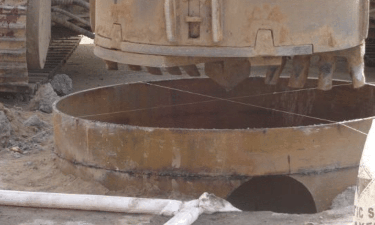
Casings with a pile diameter of 1m are made of 8mm steel plates; casings with a pile diameter of 1.5m are made of 10mm steel plates. Its inner diameter is 20cm larger than the hole diameter, and the height is generally 3.5m. To increase rigidity and prevent deformation, a stiffening rib is welded on the upper and lower ports and the outer side of the middle of the casing, and the stiffening ribs are welded with Φ20 steel bars. The top of the casing is 0.3m above the ground. The casing is buried by the excavation method, that is, a rotary drilling rig is used in conjunction with manual excavation. The burial should be accurate, horizontal, vertical, and stable, and clay should be backfilled and compacted around the casing. The center line of the drill guide rod, the center line of the rotary disk, and the center line of the casing should be kept in the same straight line. The deviation between the center of the casing and the center of the designed pile position shall not be greater than 20mm, and the verticality deviation of the steel casing shall not be greater than 0.5%, to ensure that the drilling rig works smoothly along the vertical direction of the pile position.
The rotary drilling rig is positioned by self-tracking, the center point of the drill bit is aligned with the center of the pile position, and the drill mast is adjusted to be vertical before drilling. Its working cycle is hole alignment → drill drop → drilling → drill lifting → reverse unlocking → lifting the drill rig to rotate and unload soil → hole alignment again. Zero the depth gauge each time you drill to check the drilling situation. Check whether the wire rope is in the drum groove in each cycle (check through the rear window), check whether the wire rope has burrs or broken strands, and replace it in time if necessary. Mud wall protection is used for the formation during drilling. Two ZL400-type pulping machines are used for mud preparation. The mud is prepared according to the specified mix ratio. The mixing time for each plate of bentonite is 3 minutes, and the addition error of various materials shall not exceed 5%.
The main materials are selected as follows: Bentonite: Use high-quality bentonite.
Water, dispersant (industrial soda ash), flocculant (polyacrylamide)
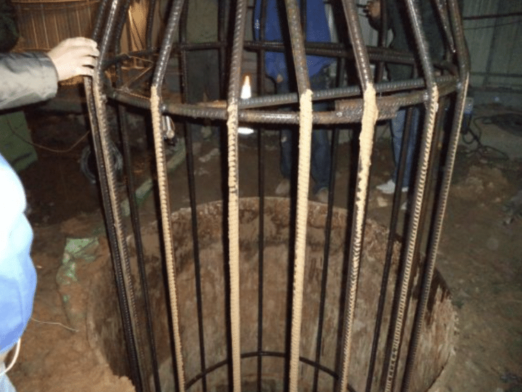
(1) Inspection of hole diameter and hole shape: The hole diameter inspection is carried out after the pile hole is formed and before the steel cage is lowered. The steel cage is used for inspection. The steel cage is made of Φ28 threaded steel. Its outer diameter is equal to the steel cage diameter plus 100 mm, but not greater than the designed hole diameter of the drilled hole. The length is equal to 6 times the hole diameter. A stiffening hoop is set every 1.5 m inside. The stiffening hoop is fixed with a cross support. During inspection, the cage is lifted, the center of the hole is aligned with the lifting steel rope, and it is slowly put into the hole. If it is unobstructed from top to bottom, it means that the hole diameter is greater than the given cage diameter and the verticality of the hole meets the requirements.
(2) Inspection of hole depth and sediment at the bottom of the hole: The hole depth and sediment at the bottom of the hole are inspected with a standard hammer. The hammer is generally a conical hammer with a hammer bottom diameter of 13cm to 15cm, a height of 20 to 22cm, and a mass of 4kg to 6kg. It is hung on the measuring rope and checked by hammering with its weight. The measuring rope is calibrated with a steel ruler. Before pouring concrete, the thickness of the sediment at the bottom of the hole is checked. The thickness is required to be no more than 5cm. It is strictly forbidden to use the method of deepening the drilling depth instead of cleaning the hole.
(1) The steel cages are made in sections in the steel bar factory. The steel bars in the sections are connected by sleeves. The sections are connected by single-sided welding at the construction site. The steel cages are formed by the mold-forming method and are manually wrapped and tied. To ensure that the steel cages do not deform during transportation and hoisting when making the steel cages, Φ28 steel bars are used to make cross steel bars and welded with the reinforcing ring bars. The steel cages should be made strictly according to the design drawings. The allowable deviations are main bar spacing ±10mm, stirrup spacing ±20mm, skeleton outer diameter ±10mm, skeleton inclination ±0.5%, skeleton protective layer thickness ±20mm, skeleton center plane position 20mm, skeleton top elevation ±20mm, skeleton bottom elevation ±50mm. The steel cages are made in sections of 8m each. The main bars of the steel cages made in sections are welded and should comply with the “Concrete Structure Engineering Construction and Acceptance Code” GB50204-2002 and related specifications.
(2) Steel skeleton protective layer The thickness of the steel skeleton protective layer is 60mm. After the steel cage is welded, φ20mm positioning steel bars should be welded outside the steel cage and installed according to the designed length and position.
(3) Installation of ultrasonic detection tube and grouting pipe According to the design requirements, three ultrasonic detection tubes with a diameter of 57mm and a wall thickness of 3.0mm are buried in each pile. The specific construction measures are as follows:
① The ultrasonic detection tube and grouting pipe in the steel cage need to be fixed with positioning bars. φ10 steel bars are welded on the skeleton with a length of 45cm. One is evenly arranged every 3m on the periphery of the ultrasonic detection tube, and it is hoisted in sections. The joints are connected with special joints;
② The bottom and top of the ultrasonic detection tube should be sealed with special wire plugs;
③ To facilitate pile foundation detection and post-pile foundation pressure drop construction, the top of the ultrasonic detection tube is required to be 50cm above the ground.
④ For piles 45m and above, three side grouting valves are set, and for piles below 45m, two side grouting valves are set. The layout principle of the side grouting valves is: the lowest one is 12m~18m away from the bottom of the pile, and the highest one is 8m~15m away from the top of the pile. The vertical spacing of each side grouting valve is 12m. Each grouting valve corresponds to a grouting nozzle. The grouting pipe adopts a DN25 steel pipe. The outer side of the grouting nozzle pipe is perforated (hole spacing 10cm) and sealed with waterproof plastic tape. When grouting the pile side, the slurry is injected into the soil within a certain range of the pile-soil interface above the grouting point through infiltration and splitting. The grouting pressure depends on the nature and depth of the stratum. The weathered rock pressure is the highest and the soft soil pressure is the lowest.
Before using the catheter, check whether there is air leakage, water leakage, and deformation, whether the joints are firm and reliable, measure the actual length of the catheter after assembly, and regularly perform extension watertight tests and joint tensile tests. It can only be used after meeting the requirements.
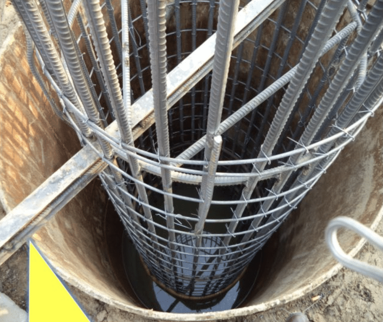
(1) When using a steel transport vehicle for transportation, ensure that a support point is set at each reinforcement point, and the height of each support point is equal; when using manual lifting, set more lifting rods, and ensure that the lifting rods are inserted near the center of the frame at the reinforcement point, and each lifting rod is evenly stressed. When the steel cage is hoisted by a crane, set two lifting points at the top (the position of the top reinforcement bar) for vertical lifting, and set one lifting point (the position of the reinforcement bar) in the middle of each section of the steel cage for turning over and lifting. Set one more Φ20 reinforcement bar at the lifting point;
(2) After the steel cage is lifted to 0.3m~0.5m from the ground, check whether the steel cage is stable. According to the distance between the tail of the steel cage and the ground, command the auxiliary crane to cooperate with the hook at any time. The main hook slowly lifts and the crane and auxiliary crane cooperate to keep the distance between the steel cage and the ground, and finally make the steel cage perpendicular to the ground.
(3) Command the crane to lift the cage into the hole and position it. The crane should rotate smoothly and pull the traction rope on the steel cage. If the steel cage is stuck in the hole during lowering, it should be hoisted out and checked before lowering. It should not be forced into the hole.
(4) When the steel cage is lowered to the B lifting point, stop lowering and remove the wire rope and clamp ring at the B lifting point. When the steel cage continues to be inserted downward to the A lifting point, stop lowering and insert the channel steel to fix the steel cage on the top of the casing, and then remove the wire rope and clamp ring at the A lifting point.
(5) After the first section of the steel cage is hoisted, lift the second section to the hole and weld the main reinforcement. During welding, align the upper and lower main reinforcements and keep the upper and lower axes of the steel cage consistent: first, connect two joints in one direction, then lift them slightly to make the upper and lower sections of the steel cage vertical under the action of their weight, and then connect all other joints. The joint positions must be staggered by 50% of the number of joints. The distance between two adjacent joints should not be less than 35 times the diameter of the main reinforcement and not less than 50cm. The welding length is 10d for single-sided welding. Install the sonic detection pipe and grouting pipe before welding the steel cage. After all the main bars are welded, the stirrups are wrapped and spot-welded in a plum blossom shape. They can be lowered at a uniform speed only after acceptance. The steel cage is hoisted from the lowest section upwards until the entire steel cage is hoisted.
(6) When the uppermost steel cage is lowered to the hole position, the steel cage is temporarily supported at the hole position with channel steel. According to the elevation of the tube top and the elevation of the steel cage top, the length of the suspension bar is calculated and welded on the main steel cage bars. The suspension bar is made of Ф20 round steel, and a 20-diameter ring is made of Ф20 round steel at the top of the suspension bar as the ear bar. Then hang the hook on the suspension bar and slowly lower it to the designed position. Insert two parallel channel steels in the top hoisting ring of the steel cage and place them horizontally on the sleepers. Hang the entire cage on the square wood on both sides of the top of the casing to ensure the accurate position and height of the steel cage. The channel steel is [No. 20, each 3m long.
The conduits should be lowered in sequence, and the order of the conduit installation, the length of each conduit, and the number of conduits should be recorded. When the conduit is lowered, it should be prevented from colliding with the steel cage. The conduit support frame is made of steel and is supported on the drilling platform to support the suspended conduit.
⑴ Purpose of hole cleaning: Due to the placement of the steel cage and conduit, sediment will be generated at the bottom of the hole during this period. Therefore, after the steel cage and conduit are in place, the conduit is used to clean the hole.
⑵ Hole cleaning method: Install an elbow and a leather cage at the top of the conduit, use a pump to press the mud into the conduit, and then replace the sediment from the bottom of the hole along the conduit.
⑶ Hole cleaning standard: The hole depth meets the design requirements, the mud density at the bottom of the hole is controlled at 1.03~1.1, the viscosity is controlled at 17~20s, the sand content is ≤2% and the sediment thickness is re-measured within 50mm before pouring underwater concrete. Sediment measurement After the pile hole is cleaned, it meets the sediment requirements at the bottom of the friction pile hole. The thickness of the bottom sediment is measured by a standard hydrographic measuring rope with a conical hammer. The weight of the hammer is ≥1kg and the sediment thickness is not more than 5cm. The starting point for calculating the bottom sediment of the hole should be 1/2 of the height of the cone at the bottom of the hole.
When the sediment thickness does not meet the design and specification requirements, the hole must be cleaned according to the plan requirements.
(1) Combined with the transportation distance from the concrete mixing station to the construction site, the impact of the transportation distance on the concrete slump should be fully considered during the pouring process. The concrete pouring of the pile body should be carried out within half an hour after the secondary hole cleaning is completed and the sediment thickness and mud-specific gravity are checked to meet the requirements, and the pouring should be continued until the pile is completed.
(2) The initial pouring volume should allow the conduit to be buried in the concrete for more than 1.0m at a time. The quantity of the first batch of concrete pouring is determined by on-site calculation and should be able to meet the needs of the initial burial depth of the conduit.
(3) The concrete mix ratio should follow the following principles: the sand content of the concrete should be 0.43-0.47; the slump should be 180-220mm; the amount of cementitious material should be 280-400kg/m3, and the maximum water-cement ratio should be 0.55.
(4) Before pouring concrete, first hoist in the water stopper, which is 20-25mm smaller than the inner diameter of the conduit. Before pouring concrete, hang it in the conduit with wire. When the concrete reaches the first pouring volume, cut off the stopper and release it. During the initial pouring, the buried depth of the conduit is greater than 1.0m. Before each lifting of the conduit, measure the height of the concrete surface of the inner and outer diameters of the conduit, fill in the underwater concrete pouring record sheet, and draw the underwater concrete pouring curve. When the concrete surface in the hole is about to approach the bottom of the steel cage, prevent the steel cage from floating up. When the pouring concrete surface is close to the design elevation, pay attention to the concrete surface to make it meet the design requirements. Each time the conduit is removed, it should be rinsed clean in time. After pouring, the funnel, slurry storage bucket and other special tools must be rinsed. The pouring work must be carried out continuously, and the time for loading and transporting the bucket, lifting the pipe, and removing the pipe should be compressed as much as possible. It is strictly forbidden to stop work in the middle. The slump of concrete should be measured before pouring concrete, and the slump of concrete should be controlled at 180-220mm. The filling coefficient of concrete pouring is 1 to 1.3. Three groups (3 blocks in each group) of test blocks (cubes with a side length of 100 mm) are sampled for each bored pile. After the concrete pouring is completed, the catheter is slowly pulled out. Before the catheter is lifted off the concrete surface, it must be repeatedly inserted to avoid hollow piles. Underwater concrete is constructed continuously without interruption, and the pouring process must be recorded in detail. All faults during the pouring process must be recorded and filed.
1. Concrete pouring can only be carried out after all tests and tests are passed. All tests and tests must be carried out during the entire construction process;
2. The hopper capacity used for initial concrete pouring must meet the requirement that the initial conduit burial depth is greater than 1m;
3. During the pouring process, always pay attention to the height of the concrete surface to ensure that the buried depth of the conduit is within the range of 2 to 6 meters;
4. When the buried depth of the conduit exceeds the allowable range, pull out the conduit in time, and the pulled-out conduit should be rinsed clean and neatly stacked in time.
Ultrasonic testing is carried out 7 days after the pile is completed. The testing requirements are as follows:
(1) 100% of bored piles should be buried with acoustic testing tubes, and the number of piles subjected to ultrasonic testing should not be less than 50%
(2) The sampling rate of high-strain dynamic testing should not be less than 5% of the total number of piles under similar conditions, and should not be less than 5 piles.
(3) 100% of the pile foundation should be tested for integrity. According to this requirement, piles that have not been subjected to ultrasonic testing or high-strain dynamic testing should be subjected to low-strain reflection wave testing.
1) Construction process principle: Use a grouting pump to pressurize the prepared cement slurry into the pipe inside the pile body, and inject it into the surrounding medium through the grouting valve at the bottom of the pile or the side of the pile. When grouting the pile bottom, it is injected into the sediment at the bottom of the pile and the surrounding soil within a certain range through infiltration (coarse-grained soil) and splitting (fine-grained soil), and expanded to 10-20m or even higher above the bottom of the pile on the weak interface of the pile and soil. Three side grouting valves are set for piles of 45m and above, and two are set for piles of less than 45m. The layout principle of the side grouting valve is: the bottom one is 12m-18m away from the bottom of the pile, and the top one is 8m-15m away from the top of the pile. The vertical spacing of each side grouting valve is 12m. Each grouting valve corresponds to a grouting nozzle. The grouting pipe adopts a DN25×3.5 steel pipe. The outer side of the grouting nozzle pipe is perforated (hole spacing 10cm) and sealed with waterproof plastic tape. When grouting the pile side, the slurry is injected into the soil within a certain range of the pile-soil interface above the grouting point through infiltration and splitting. (
2) Working function:
a. Solidification effect of sediment and mud skin: For coarse-grained sediment, cement slurry is solidified into medium-low strength concrete, and for fine-grained sediment or loose soil, it is solidified into a mesh-like stone composite soil, thereby increasing the end resistance. The mud skin on the surface of the pile body is solidified by the physical and chemical action of the cement slurry, thereby increasing the side resistance.
b. Infiltration and bonding effect: When the pile bottom and pile side are coarse-grained soil (pebbles, gravel, coarse, and medium sand), the strength is significantly improved due to the infiltration and bonding effect of cement slurry.
c. Split reinforcement effect: When the pile bottom and pile side are fine-grained soil (cohesive soil, silt, fine sand), splitting and injection are performed to form a mesh-like reinforced composite soil with high strength and stiffness. For unsaturated fine-grained soil, the soil is strengthened by splitting-compacting grouting.
d. Bottom-expanding and diameter-expanding effect: An enlarged head is formed at the bottom of the pile, and a 10-50 mm thick cement stone layer that is tightly fixed to the pile body is formed on the surface of the pile, which has the effect of expanding the bottom and diameter.
⑴ Installation of grouting equipment and grouting pipe
① The grouting system consists of a slurry agitator, a slurry storage bucket with a filter, a grouting pump, a pressure gauge, a high-pressure hose, a grouting conduit pre-buried in the pile, and a one-way valve.
② Selection of grouting pump system The grouting pump is the main equipment for post-grouting. The grouting pump generally uses a grouting pump with a rated pressure of 6-12mpa and a rated flow of 30-100L/min. The pressure gauge range of the grouting pump is 1.5-2.0 times the rated pump pressure. The capacity of the slurry agitator matches the rated grouting volume. A cement slurry filter should be installed at the slurry outlet of the agitator to prevent cement lumps from entering the slurry storage barrel and being sucked into the grouting conduit, causing pipe blockage or bursting. The grouting pump and the grouting pipe are connected by a reinforced hose that can withstand more than 2 times the maximum grouting force.
(2) Preparation of grout: Ordinary silicate cement with the same strength grade as the cement for the cast-in-place pile is mixed with clean water to form a cement slurry with a water-cement ratio of 0.6. Before the post-grouting operation, a test grouting should be carried out to adjust and optimize the process parameters such as the slurry water-cement ratio, grouting pressure, and grouting volume, and finally determine the process parameters.
⑶ In the post-grouting construction of the unplugged cast-in-place pile, the pile bottom is not filled with gravel and the unplugging time is advanced. The unplugging is carried out within 3 to 14 days after the concrete is poured. After the unplugging, the grouting pipe is flushed with clean water until the clean water overflows, and then the grouting pipe is re-sealed with a plug.
⑷ Construction time of post-grouting: Grouting starts 7 days after the pile foundation is ultrasonically tested, first side grouting, then pile bottom grouting. The order of pile side grouting is first top and then bottom, first periphery, and then middle. The time interval between pile side grouting and pile bottom grouting is 3 to 6 hours.
(1) Pile end grouting When grouting the pile end, use the sonic detection pipe as the grouting pipe, tie it to the inner side of the steel cage, and follow the steel cage into the bottom of the hole. The sonic detection pipe is arranged in an equilateral triangle with an outer diameter of 57mm and a wall thickness of 3.0mm. The top is 50cm above the ground and sealed with a plug to prevent mud from entering. Select two sonic detection pipes as grouting pipes, and use a reducer (from 57mm to 25mm), a tee and a one-way valve to connect a 32mm flexible high-pressure plastic pipe with steel wire as the grouting nozzle pipe. The grouting nozzle pipe is arranged in a circle around the pile body and holes are drilled on the pipe wall at intervals of 10cm. Finally, a layer of rubber band is wrapped on the outside (wrapped with a layer of transparent tape) to seal it. One of the two pipes is used as a spare pipe to be used when the grouting pipe fails.
(2) Pile side grouting For piles 45m and above, three side grouting valves are set, and for piles less than 45m, two side grouting valves are set in the following positions: the lowest one is 12-18m away from the pile bottom, and the highest one is 8-15m away from the pile top. The vertical spacing of each side grouting valve is 12m. Each grouting valve corresponds to a grouting pipe, which is a DN25 steel pipe tied to the outside of the steel cage. The steel pipe is connected to a tee, a one-way valve, and a Ф32 flexible high-pressure plastic pipe with steel wire as a grouting nozzle, and is arranged at the same level as the pile bottom grouting nozzle.
(3) Cement slurry preparation Mark the corresponding scale of cement slurry with a certain water-cement ratio on the outer wall of the mixer barrel. When preparing cement slurry, first add a certain amount of water to the mixer, then add a certain amount of cement while stirring, and then add water according to the water-cement ratio. After the cement slurry is stirred, it reaches the corresponding scale. The stirring time is not less than 2 minutes. The slurry is filtered with a 3×3mm filter. The slurry uses pure cement slurry. After the cement slurry is stirred, it is filtered and placed in the slurry storage barrel. The cement is also ensured to be continuously stirred in the slurry storage barrel.
(4) Grouting pressure and control requirements 4.1 Grouting should meet the pressure and duration requirements required by the design. The grouting pressure on the pile side is 2~2.5MPa, and the grouting pressure on the pile bottom is 2~4MPa. The holding time: after the pressure reaches the design value, the holding time should not be less than 5min. 4.2 To reduce the loss of grouting pressure caused by the pipeline system, the distance between the grouting pump and the grouting orifice should not be greater than 30m, and ensure that the grouting pipeline does not bend during the grouting process.
4.3 The specification requires that the main flow rate should generally be controlled at 75L/min. To ensure the grouting effect, the maximum rated pressure of the grouting pump should be greater than 10MPa and the flow rate should be greater than 5m3/h. 4.4 Grouting volume (cement consumption) design, that is, for piles with a pile diameter of 1.5m: the cement consumption for pile side grouting is 1.5t/pass; the cement consumption for pile bottom grouting is 3.5t/pass; the total cement consumption for grouting is 6.5t for a single pile when two grouting valves are measured, and 8t for three grouting valves. For piles with a pile diameter of 1.0m: the total cement consumption for grouting is 2.9t for a single pile when two grouting valves are measured, and 3.5t for three grouting valves. The grouting volume of the first pile needs to be multiplied by a coefficient of 1.2.
⑸ The grouting process is controlled by the “double control” method. Grouting termination conditions can be terminated when one of the following conditions is met:
① The total amount of grouting and the grouting pressure meet the design requirements;
② For each grouting, the grouting volume reaches the design value, but the grouting pressure does not reach the design value. At this time, change to intermittent grouting, and then inject 30% of the design value of cement slurry;
③ For each grouting, the grouting pressure reaches the design value and after holding the load for 5 minutes, the grouting volume is less than the design value. At this time, it is sufficient to ensure that the grouting volume is not less than 80% of the design value.
⑹ The grouting operation process record should be complete, and the various process parameters of the post-grouting should be checked frequently. When abnormal conditions are found, the cause should be immediately identified and measures should be taken before continuing grouting.
The post-grouting of pile foundation must ensure that the grouting pressure value and grouting volume meet the design requirements.
⑴ During the post-grouting construction process, the various process parameters of the post-grouting should be checked frequently, and if any abnormality is found, treatment measures should be taken immediately.
⑵ During the grouting operation, measures should be taken to prevent pipe bursting, pipe throwing, leakage, and other safety measures.
⑶ The front-end observation personnel and the back-end pump operation personnel have a clear division of labor and maintain close contact to deal with unexpected situations during the grouting process promptly.
⑷ The grouting pump pressure gauge should be calibrated regularly.
⑸ Admixtures can be added to the cement slurry according to actual needs.
⑹ During the construction process, measures should be taken to prevent dust from polluting the environment.
(7) Clean the acoustic test pipe with clean water before acoustic testing.
Special situation handling and preventive measures
3.1 Collapse during drilling
⑴ Phenomenon During the drilling process, if the water level in the hole suddenly drops, fine bubbles will appear at the hole mouth. This indicates that the hole has collapsed.
⑵ Hazards prevent normal drilling. It is easy to cause drill drop and drill burial accidents.
⑶ Cause analysis
① The mud density is not enough or other mud performance indicators such as viscosity and colloid rate do not meet the requirements, and a solid mud skin cannot be formed on the hole wall; or the mud density cannot be adjusted with the change of geological conditions, resulting in unstable hole wall.
② Due to hole cleaning, the mud is not replenished in time or pressurized water appears in the hole. Or when the drilling hole passes through a strong permeable layer such as gravel or the hole wall encounters a quicksand layer, causing the water head height in the hole to be lower than that outside the hole, the water pressure pressing on the hole wall is reduced, causing the hole to collapse.
③ The casing is buried too shallowly, or the ground near the hole mouth becomes soft due to water immersion, and the hole mouth collapses, causing the casing to leak and form a collapsed hole.
⑷ Preventive measures
① When drilling in loose silty soil or quicksand, mud with a larger specific gravity and higher viscosity should be used, and the penetration speed should be slowed down.
② According to different geology, adjust the mud-specific gravity to ensure that the mud has sufficient viscosity, ensure the water level difference inside and outside the hole, and maintain the stability of the hole wall.
⑸ Preventive measures:
① When the hole mouth collapses, the casing can be immediately removed and reburied, and the casing can be re-drilled. When the collapsed hole is not deep, the deep-buried casing method can be used to compact the soil around the casing and re-drill.
② When the hole collapses, determine the collapse location and backfill the mixture of sand and clay (or gravel and loess) to 1-2m above the collapsed hole. If the collapse is serious, it should be backfilled completely, and drilling can be continued after the backfill material is settled and compacted. 4.2 The bottom sedimentation of the hole is too thick after the hole is cleaned (1) The phenomenon adopts the jet hole cleaning method; or the method of deepening the bottom depth of the hole is used instead of cleaning the hole.
⑵ The purpose of hole cleaning is to extract and replace the mud in the hole and reduce the relative density of the mud in the hole. Both the jetting method and the deepening of the hole bottom failed to achieve the purpose of hole cleaning, which not only reduced the bearing capacity of the pile tip, but also easily caused mud or interlayers in the pile body concrete, and even pile breakage.
⑶ Cause analysis
① When jetting hole cleaning, excessive pressure of water (or wind) can easily cause hole collapse, and too low pressure can not effectively turn over the sediment at the bottom of the hole.
② Deepening the bottom of the hole cannot reduce the relative density of the mud in the water in the hole. At the same time, the increased bearing capacity of deepening the bottom of the hole cannot compensate for the loss of bearing capacity caused by not cleaning the hole.
⑷ Treatment method
① Hole cleaning should be selected according to design requirements, drilling methods, machine equipment conditions, and soil conditions, and should achieve the purpose of reducing the relative density of mud, removing drilling slag, removing sediment layer, or minimizing its thickness.
② For various drilling methods, the extraction method is the most thorough. When cleaning the hole, attention should be paid to always maintaining the water head in the hole to prevent hole collapse.
③After the hole is cleaned, the mud indicators are measured. The sand content, viscosity, and relative density of the mud should meet the requirements of the quality standards.
⑴ Phenomenon The pipe is blocked.
⑵ Hazards cause interruption of pouring, which makes it easy to form high-pressure airbags during pouring after interruption. In severe cases, it is easy to develop into broken piles.
⑶ Cause analysis
① Due to various reasons, the concrete is segregated and the coarse aggregate is concentrated, resulting in inverted blockage.
② Because the pouring time lasts too long, the initially poured concrete has initially solidified, increasing the resistance of the concrete in the pipe to fall, causing the concrete to be blocked in the pipe.
⑷ Preventive measures:
① The slump of the poured concrete is easy to be between 180-220mm, and it is guaranteed to have good workability. No significant segregation and water seepage occur during transportation and pouring.
② Ensure continuous pouring of concrete, and interruption of pouring should not exceed 30 minutes.
⑸ Treatment method: When the pipe is blocked soon after the pouring begins, you can use a long pole to punch, tamp, or vibrate the conduit. If there is no effect, pull out the conduit, use an air suction machine, or grab to clear the concrete that has been poured into the bottom of the hole, replace the conduit, prepare enough concrete reserves, and pour again.
⑴ Phenomenon: After the steel cage is put into the hole, it has been fixed, but when the concrete is poured into the hole, the steel cage floats upward.
⑵ Hazard: Once the steel cage floats, it is impossible to return it to its original position, thereby changing the number of reinforcements in the pile body and damaging the bending strength of the pile body.
⑶ Cause analysis: When concrete is poured downward from the funnel along the conduit, the potential energy of the concrete generates a kind of jacking force. This jacking force varies with the size of the concrete potential energy during pouring, the speed of pouring, the fluidity of the first batch of concrete, and the surface elevation of the first batch of concrete. When the jacking force is greater than the weight of the steel cage, the steel cage will be pushed up by the float.
⑷ Preventive measures
① For friction piles, several main bars of the steel cage skeleton should be extended to the bottom of the hole, and the upper end of the steel skeleton should be connected and fixed to the casing at the hole mouth.
② During pouring, when the concrete surface approaches the bottom of the steel cage, the concrete pouring speed should be slowed down, and the guide tube should be kept at a large distance to reduce the impact on the steel cage.
③ After the concrete enters a certain depth of the steel cage, the guide tube should be properly lifted so that the steel cage has a certain depth at the lower end of the guide tube. However, it should be noted that the guide tube should be buried in the concrete surface for not less than 2m.
⑴ Phenomenon During the pouring of underwater concrete, it is found that the mud water level in the casing suddenly rises and overflows the casing, and then suddenly drops and bubbles appear, which is a sign of collapse. If the concrete surface detected by the depth hammer is much different from the original depth, it can be determined as a collapse.
⑵ Hazards cause the pile body to expand in diameter and the pile body concrete to be mixed with mud; in severe cases, it will cause a pile break accident.
⑶ Cause Analysis
①During the pouring of concrete, the water head inside and outside the hole failed to maintain a certain height difference.
②Water leakage around the blade foot of the casing; heavy objects are piled outside the hole or there is machine vibration, causing the hole wall to collapse during the pouring of concrete.
③When the conduit is stuck in the steel cage and the pipe is blocked, the hole is prone to collapse.
⑷ Treatment Method
①During the pouring of concrete, various measures should be taken to stabilize the water level in the hole and prevent the casing and the hole wall from leaking.
②Use a mud suction machine to suck out the soil that has collapsed into the hole, while maintaining or increasing the water head height. If there is no more collapse, continuous pouring can be carried out.
③If the collapse continues with the above methods, or the collapsed hole is deep, it is advisable to pull out the conduit and steel cage, backfill with clay, and re-drill.
⑴ Phenomenon The conduit is difficult to lift from the concrete poured into the hole, or even cannot be pulled out, resulting in a buried conduit accident.
⑵ The buried conduit causes the construction of underwater concrete pouring to be interrupted, which is easy to develops into a pile break accident.
⑶ Cause Analysis
①During the pouring process, the conduit was buried too deep in the concrete, usually more than 6m.
②Due to various reasons, the conduit was not lifted for more than 0.5 hours, and part of the concrete was initially set, holding the conduit.
⑷ Preventive measures
①The conduit joint should be a bayonet type, which can shorten the conduit residence time caused by unloading the conduit. Each batch of concrete is mixed with a retarder, and measures are taken to speed up various speeds.
②As the concrete is poured, the conduit is frequently lifted so that the buried depth of the conduit is not more than 6m.
⑸ Treatment methods
①When burying the conduit, use a chain pulley, jack, and winch to try to pull it out.
②If it cannot be pulled out, the conduit can be pulled out with force, and then treated as a broken pile.
⑴ Phenomenon There is a mud or drill slag layer between the concrete layers poured twice in succession. If it exists in part of the cross-section, it is mud inclusion; if there is a mud layer in the entire cross-section or a layer of concrete is completely separated, and there is no cement slurry bonding, it is a broken pile.
⑵ Hazards of mud inclusion and broken piles make the pile concrete discontinuous, unable to withstand the horizontal shear force caused by bending moment and earthquake and make the pile scrapped.
⑶ Cause analysis
① When pouring underwater concrete, the slump of the concrete is too small, the aggregate grading is poor, the coarse aggregate particles are too large, and the concrete segregates before or during pouring; or water enters the conduit, causing the concrete of the pile body to be interrupted.
② During pouring, the conduit is blocked and not handled properly; or the conduit is stuck in the steel cage, buried in the conduit, and serious collapse is not handled properly during pouring, which will evolve into a serious accident of serious mud inclusion in the pile body and interruption of the concrete pile body.
③ The hole is not cleaned thoroughly or the pouring time is too long, the first batch of concrete has been initially set, and the top layer of concrete that continues to be poured is mixed with mud, or water enters the conduit, and the general collapse of the poured concrete will produce a section with mud and slag in the two layers of concrete.
⑷ Preventive measures
① The slump of concrete should be strictly controlled according to the design or specification requirements, and the initial setting time of concrete should be extended as much as possible (such as using cement with slow initial setting, adding retarders, using pebbles, increasing the sand ratio, controlling the maximum particle size of stones, etc.)
② Before pouring concrete, check whether the equipment such as conduits, concrete tankers, mixers, etc. are normal, and have spare equipment and conduits to ensure that concrete can be poured continuously.
③ Select the commercial concrete supply route and spare route, use radio and intercom to coordinate the unified dispatch, and change the route in time when the road is congested to ensure a timely and rapid supply of commercial concrete.
④ When choosing a commercial concrete supply station, try to choose one that is close to the construction site, and determine a spare commercial concrete supply station for emergency response.
⑤ Pour the concrete and lift the conduit at the same time, and do the continuous pouring, frequent measurement, and frequent pipe removal. Keep track of the buried depth of the conduit at any time to avoid burying the conduit too deep or too shallow.
⑥ Take measures to avoid conduit jams and hanging steel cages; avoid the occurrence of common quality problems such as blocked conduits, buried conduits, collapse holes during pouring, and water inflow to conduits.
⑸ Treatment methods
① When broken piles or mud inclusions occur at the top of the pile, they can be removed. Then the casing is extended and pressed below the poured concrete surface. Pump out water, remove slag, and connect the piles.
② Use a geological drill to drill core samples. If there are honeycombs, looseness, or grouting (when the core sampling rate is less than 40%), the pile body concrete has local concrete looseness or mud inclusions and local broken piles, the grouting reinforcement method should be used.
③ For serious mud inclusions and broken piles, consult with the design unit and issue a treatment plan for post-processing.
⑴ Several situations that often occur during normal grouting:
1) The pressure gradually increases but does not reach the design pressure. This may be due to the formation of vein-splitting penetration of the slurry in the clay, or the low concentration of the slurry, long gelation time, or partial overflow of the slurry.
2) The pressure does not rise after the grouting starts and even shows a downward trend from the initial pressure value, which may cause the slurry to overflow.
3) The pressure rises and then suddenly drops. This may be because the slurry overflows from around the grouting pipe, or the injection speed is too high, disturbing the soil layer, or encountering a weak part of the gap.
4) The pressure rises quickly, but the speed cannot go up, indicating that the soil layer is dense or the gel time is too short.
5) The pressure rises regularly. Even if the allowable pressure is reached, the grouting speed is also normal (with little change), which indicates that the grouting is successful.
6) The pressure rises and then drops, and then rises again and reaches the predetermined required value. It can be considered that the gap in the 3rd case has been filled with slurry, which is also successful.
Pile foundation is a hidden project deep underground. Its quality cannot be directly inspected from the outside. During the entire construction process, effective quality control measures must be taken to ensure that the quality of the cast-in-place piles fully meets the design requirements. The quality control points of the pile foundation include pile position, pile diameter, pile inclination, pile length, pile bottom sediment thickness, pile top slag thickness, pile structure, concrete strength and homogeneity, steel cage, etc.
4.1 Pile position control The construction site is muddy. After the pile position is set, it cannot be preserved for a long time. After the casing is buried, it needs to be proofread. To ensure the quality of the pile position, a precise measurement method can be adopted, that is, positioning with a total station, and re-measurement after the casing is buried. A welded coordinate frame is used to calibrate the center of the casing to keep it consistent with the center of the pile position. The inclination of the piles of adjacent constructed piles must be known in advance; when the completed cast-in-place piles incline, especially when the piles on both sides have been cast, the design, supervision, and construction units should jointly determine the opening position of the unconstructed piles to ensure that the construction of this pile does not damage the piles on both sides.
4.2 Pile inclination control The buried casing adopts the cross-crossing legal centering at the upper and lower ends of the inner diameter of the casing. Through the two center points, the casing can be ensured to be vertical. The hole inclination is measured in time during drilling to ensure that the hole inclination is less than 1%. If the hole inclination is too large, take corrective measures immediately.
4.3 Pile diameter control The reasonable selection of drill bit diameter according to the formation conditions plays an important role in pile diameter control. The hole diameter can be 5 to 10 cm larger than the drill bit diameter. In loose formations such as sand layers and gravel, to prevent collapse
4.4 Pile length control During construction, the casing mouth elevation, and various design elevations must be clarified and converted correctly. When drilling in the soil layer, the starting point of the conical drill bit should be accurate and adjusted according to different soil conditions. The length of the machine should be measured accurately. The elongation value after loading should be considered, and any errors should be corrected in time.
4.5 Pile bottom sediment control When drilling in soil, sand, or gravel layers, the hole is generally cleaned by slurry replacement. Reasonable mud performance indicators should be selected. When replacing the slurry, the specific gravity of the slurry returned from the borehole should be less than 1.10 to keep the bottom of the hole clean and free of sediment. The thickness of the bottom of the hole should be strictly implemented by the hole cleaning standards to prevent excessive sediment from affecting the pile length and the quality of the poured concrete.
4.6 Pile top control The poured concrete flows out through the bottom of the conduit, flushes the sediment at the bottom of the hole, and fills its space. As the pouring continues, the concrete surface continues to rise. Since the sediment has a smaller specific gravity than concrete, it always floats on the top, forming pile-top scum. The compactness of the scum is poor, which is significantly different from concrete. When the concrete is poured into the last bucket, the thickness of the slag should be accurately determined. Calculate and adjust the concrete capacity of the last bucket. After pouring, check the height of the pile top again. When it meets the design requirements, remove the guide tube, otherwise it should be supplemented.
4.7 Concrete strength control According to the design mix ratio, conduct concrete trial mixing and rapid maintenance and inspection. Make necessary adjustments to the concrete mix ratio design. Strictly follow the specifications to control the quality of cement, sand, and stone. Those with quality assurance certificates should also be checked. During the pouring process, frequently observe and analyze the concrete mix ratio, test the slump in time, and add an appropriate amount of admixtures to save cement during the trial mixing, reduce the amount of water, and improve the strength of the concrete. Strictly make test blocks according to regulations, take samples at the mixer outlet or pouring site, and ensure the quality and quantity of sampling. A group of concrete test blocks consists of 3 100mm×100mm×100mm cubes.
4.8 When the reinforcement cage of the pile structure is manufactured and installed, the spacing between the reinforcements shall not exceed the error allowed by the specification. When the main reinforcement is overlapped by mechanical joints, overlap welding, and bar welding, it shall be strictly carried out by the requirements of the specification. The positioning block is the main measure to control the thickness of the protective layer and cannot be omitted. All data of the reinforcement cage shall be inspected and recorded according to the hidden project. Ring reinforcement can be welded at the lifting part to improve the strength. The lifting steel rope should be lengthened to reduce the angle between the two ropes and prevent the deformation of the reinforcement cage during lifting. Ensure that the conduit is well sealed, and the movable conduit cannot be raised too much during pouring to prevent quality accidents such as mud inclusion and broken piles. If these accidents occur, all the conduits should be raised and put into the hole after handling.
4.9 Post-grouting quality control measures
⑴ The quality standard of pile formation shall comply with the relevant provisions of JGJ94 “Technical Specifications for Building Pile Foundations”, and the corresponding clauses of this specification shall be used for acceptance.
⑵ During the post-grouting construction process, various process parameters of post-grouting are frequently checked. The water-cement ratio is measured by spot checks on site, and the water-cement ratio is measured according to the scale on the mixing drum. The grouting pressure is checked by tracking the pressure gauge. If abnormalities are found, corresponding measures should be taken.
⑶ After the project is completed, the vertical bearing capacity and pile integrity of the single pile should be inspected under the relevant provisions of the current JGJ94 “Technical Specifications for Building Pile Foundations”.
⑷ When the main construction parameters such as grouting volume do not reach the corresponding values of the test pile, the design unit should be consulted for treatment opinions and construction treatment.
⑸ After the post-grouting construction of the pile foundation is completed, the following information should be provided: material inspection report, grouting equipment performance information, test grouting record, design process parameters, post-grouting operation record, post-grouting pile inspection and special situation handling record. Post-grouting information needs to be signed on-site.
4.10 Raw material control For each batch of raw materials such as steel bars, cement, and admixtures entering the site, the material certification documents such as the label, factory date, and factory test report should be strictly checked sampled, and reported to the supervisor. All performance indicators must meet the design requirements before they can be used. It is strictly forbidden to use unqualified or expired hardened cement. Except for admixtures, which are commissioned to be specially inspected by laboratories with corresponding qualifications for 1 to 2 times, the main requirements for sampling inspection of other raw materials are as follows:
⑴ The cement site laboratory samples and inspects every 200t of bagged cement and every 500t of bulk cement. The inspection items include strength grade, setting time, stability, and other indicators. The sampling and inspection methods are based on relevant cement standards.
(2) Sand and gravel are batched at 600t or 400m3. Any less than this number is considered as one batch. When sampling the material pile, no less than 8 points form a group of samples. Sampling test of sand and gravel materials in the mixing plant material yard, including sieve analysis and mud content, the test results correspond to the pile holes of the day.
⑶ Steel bars When the diameter of steel bars exceeds 12mm, mechanical properties and weldability performance tests shall be carried out; three steel bars are selected from each batch of steel bars after entering the site (60t per batch of the same type, same grade, same cross-sectional size, same furnace number, and same manufacturer) and a group of specimens is cut from each batch, with 3 specimens in each group. One group of specimens is used for the tensile test (yield strength, tensile strength, and elongation); one group of specimens is used for the cold bending test; one group of specimens is used for the weldability test; if one group of specimens fails the test or does not meet the standard requirements, another two groups of specimens are taken for further testing. If the test results of one group of the two groups of specimens still do not meet the requirements, the batch of steel bars shall not be accepted, or the supervisor shall review and decide to reduce the grade for non-load-bearing structures based on the test results.
⑷ Fly ash The quality of fly ash entering the site shall be tested by batch sampling. The sampling of fly ash is based on a continuous supply of 200t as a batch, and less than 200t is counted as a batch. Each batch of fly ash must be tested for fineness, loss on ignition, water demand ratio, and moisture content.
⑸ Bentonite is tested for raw materials in a sampling batch of 100t; the incoming bentonite is tested for mud mix ratio, and the mud mix ratio is provided for the mud mixing station, and the slurry mix ratio is adjusted at any time according to the changes of the incoming bentonite; the mud station mud should be inspected daily during construction, mainly testing the density, viscosity and other indicators of the mud.
⑹ The sampling and inspection batches of general liquid admixtures such as pumping agents, water reducers, antifreeze agents, etc. are all no more than 100t per batch, but special treatment is required in special cases, such as powder expansion agents, which are no more than 200t per batch. Each batch of admixtures mainly tests the compressive strength ratio, water reduction rate, setting time difference, slump retention value, and other items.
Quality inspection
During the hole-forming process, after the hole is completed, and before pouring concrete, bored piles need to be inspected periodically. The hole quality inspection items and inspection methods for bored piles are shown in the table below.
⑴ Hole position inspection After the steel casing is buried, a total station positioning inspection is used before the pile is opened.
⑵ Hole diameter and hole shape inspection The hole diameter inspection is carried out after the pile hole is formed and before the steel cage is lowered. The drill bit diameter can be measured. The drill bit with the same diameter as the designed pile is lowered into the hole from the hole mouth to the bottom of the hole. If the drill bit passes through the hole without getting stuck, it means that the hole diameter is qualified. It can also be inspected with a cage. During the inspection, the cage is lifted, the center of the hole is consistent with the lifting steel rope, and it is slowly put into the hole. If it is unobstructed up and down, it means that the hole diameter is greater than the given cage diameter.
⑶ Hole depth and bottom sediment inspection The hole depth and bottom sediment are inspected with a standard hammer. The measuring hammer generally adopts a conical hammer with a bottom diameter of 13 to 15 cm, a height of 20 to 22 cm, and a mass of 4 to 6 kg. The measuring rope must be calibrated with a calibrated steel ruler.
⑷ The verticality of the hole is checked by the drill rod inclination method.
⑸ Hole cleaning inspection After the hole is cleaned, the rope method is used for inspection and comparison of the hole. The thickness of the sediment after the hole is cleaned is not more than 50 mm.
When pouring concrete for each pile, the mixed concrete is sampled and formed, and the relevant concrete index tests are carried out indoors after the age. The number of concrete specimens formed is under the number specified in the design. The quality of the pile body after forming is tested and evaluated by ultrasonic non-destructive testing. Ultrasonic testing of the pile foundation can be carried out only 7 days after the pile is formed.
① 100% of the bored piles should be buried with acoustic testing pipes, and the number of piles tested by ultrasonic testing should not be less than 50%.
② The sampling rate of high-strain dynamic testing should not be less than 5% of the total number of piles under similar conditions, and should not be less than 5 piles.
③ The pile foundation strain should undergo 100% integrity testing. According to this requirement, piles that have not undergone ultrasonic testing and high-strain dynamic testing should all undergo low-strain reflection wave testing.
Bored cast-in-place piles have the advantages of low construction noise, and low vibration, pile length…
Bored cast-in-place piles have the advantages of low construction noise, and low vibration,…
The four major construction technologies are dry hole forming technology, slurry static pressure technology, casing…
Soil nail support is a new type of retaining structure developed in recent years for…
Pile Foundation Classification and Construction Principles 1. Classification According to Load-Bearing Piles ① Friction type…
Steel sheet pile cofferdams are suitable for basic projects such as sandy soil, gravel soil,…