Building Foundation Design Specification
1. The center distance of friction piles should not be less than 3 times the diameter of the pile body; the center distance of the expanded base cast-in-place pile should not be less than 1.5 times the expanded base diameter; when the expanded base diameter is greater than 2m, the clear distance between the pile ends should not be less than 1m. When determining the pile spacing, the impact of soil squeezing and other effects on adjacent piles during the construction process should be considered.
2. The diameter of the expanded base of cast-in-place piles should not be greater than 3 times the diameter of the pile body.
3. The depth at which the bottom of the pile enters the bearing layer should be 1 to 3 times the diameter of the pile body, determined based on geological conditions, load, and construction technology. When determining whether the pile bottom enters the bearing layer; when determining the depth, the effects of special soil, karst, and earthquake subsidence liquefaction should be considered. The minimum depth of the complete and relatively complete unweathered, slightly weathered, and weathered hard rock surrounding the rock-socketed cast-in-place pile should not be less than 0.5m.
4. When arranging pile positions, the pile foundation bearing capacity resultant point should coincide with the vertical permanent load resultant force application point.
5. The concrete strength grade of prefabricated piles should not be lower than C30, that of cast-in-place piles should not be lower than C20, and that of prestressed piles should not be lower than C40.
6. The main reinforcement of the pile should be determined through calculation. The minimum reinforcement ratio of driven precast piles should not be less than 0.8%, the minimum reinforcement ratio of static pressure precast piles should not be less than 0.6%, and the minimum reinforcement ratio of cast-in-place piles should not be less than 0.2%~ 0.65% (take the larger value for small diameter piles).
7. Reinforcement length:
1) The reinforcement length of piles subject to large horizontal loads and bending moments should be determined through calculation;
2) When there is silt soil or liquefied soil layer under the pile foundation cap, the length of the reinforcement should pass through the silt soil layer or liquefied soil layer;
3) Pile piles on sloping shores with a degree of 8 and above in seismic zones and rock-embedded end-bearing piles with pull-out resistance should be reinforced throughout;
4) For bored piles with a pile diameter greater than 600mm, the length of structural steel bars should not be less than 2/3 of the pile length.
8. The length of the pile top embedded in the cap should not be less than 50mm, and the anchoring length of the main bar extending into the cap should not be less than 30 times the diameter of the steel bar (Grade I steel) and 35 times the diameter of the steel bar (Grade II steel and Grade III steel). . For large-diameter cast-in-place piles, when one column and one pile are used, a cap platform can be installed or the piles and columns can be directly connected. The connection between piles and columns can be based on the requirements of high cup mouth foundations in Article 8.2.6 of this specification to select the cross-sectional size and reinforced columns. The length of the longitudinal reinforcement inserted into the pile body should meet the anchoring length requirements.
9. The backfilling around the cap and basement should meet the requirements for fill compactness.
Design Specifications for Foundations and Foundations of Highway Bridges and Culverts
Piles Can Be Classified According to the Following Provisions
1. Classification according to bearing characteristics.
1) Friction pile: The pile top load is mainly borne by the pile side resistance, and the pile end resistance is also considered.
2) End-bearing pile: The pile top load is mainly borne by the pile end resistance, and the pile side resistance is also considered.
2. Classify according to pile forming method.
1) Non-squeezing soil piles: They are divided into dry operation method drilling (digging) hole cast-in-place piles, mud wall protection method bored cast-in-place piles, and casing wall protection method bored cast-in-place piles.
2) Partially squeezed soil piles: divided into punched cast-in-place piles, squeezed-expanded cast-in-place piles, pre-drilled piles, open prestressed concrete pipe piles, etc.
3) Soil-squeezing piles: divided into pile sinking (hammering, static pressure, vibration-sinking prefabricated piles and closed prestressed concrete pipe piles, etc.).
Various Types of Pile Foundations Must Be Compared and Selected Based on Geological, Hydrological, and Other Conditions.
1. Drilling (digging) hole piles are suitable for all types of soil layers (including gravel soil layers and rock layers), but attention should be paid to:
1) When bored piles are used in silt and soil layers where quicksand may occur, it is advisable to make test piles first.
2) Digging piles should be used in strata with no or small amounts of groundwater.
2. Pile driving can be used in clay soil, sandy soil, and gravel soil.
The Bottom Elevation of the Cap for Various Types of Pile Foundations Should Meet the Following Requirements:
1. In frost-heaved soil areas, when the bottom surface of the cap is in the soil, its burial depth should comply with the relevant provisions of Article 4.1.1.
2. For rivers with drifting ice, the elevation should be no less than 0.25m below the bottom of the lowest ice layer.
3. When hit by a raft, other drifting objects, or a ship, the bottom elevation of the cap platform should ensure that the piles are not damaged by direct impact.
4. The elevation of the bottom surface of the cap platform should be determined according to the principles in Article 4.1.2.
For piles located in frost-heaved soil areas, if transverse tie beams need to be installed between the piles, their locations should be away from the frost-heaving layer to avoid the effects of frost-heaving force.
In the same pile foundation, unless specially designed, it is not suitable to use friction piles and end-bearing piles at the same time; it is not suitable to use piles with different diameters, different materials, and pile tip depths that are too different.
For large bridges and very large bridges with the following conditions, the bearing capacity of single piles should be determined through static load tests.
1. The penetration depth of piles is much greater than that of common piles.
2. The geological conditions are complex and it is difficult to determine the bearing capacity of the piles.
3. Piles for bridges with other special requirements.
Design Methods of “Technical Specifications for Building Pile Foundations”
Pile Foundations Should Be Designed According to the Following Two Types of Limit States:
1. Bearing capacity limit state: The pile foundation reaches the maximum bearing capacity, becomes unstable as a whole, or deforms unsuitably for continued bearing.
2. Normal service limit state: The pile foundation reaches the deformation limit specified in the normal use of the building or reaches a certain limit required by the durability.
Design grade building type:
Class A
1. Important buildings
2. High-rise buildings with more than 30 floors or more than 100m in height
3. High-rise and low-rise (including pure basement) conjoined buildings with complex shapes and a difference of more than 10 floors.
4. Frame-core tube structures above 20 stories and other buildings with special requirements for differential settlement
5. General buildings with more than 7 floors and buildings on slopes and shores with complex site and foundation conditions
6. Buildings that have a greater impact on adjacent existing projects
Class B buildings other than Class A and Class C
Class C is a general building of 7 stories or less with simple site and foundation conditions and even load distribution.
Pile foundations should be subjected to the following bearing capacity calculations and stability checks according to specific conditions:
1. The vertical bearing capacity and horizontal bearing capacity calculation of the pile foundation should be calculated respectively according to the usage function and stress characteristics of the pile foundation;
2. The bearing capacity of the pile body and cap structure should be calculated; for piles with an undrained shear strength of soil on the side of the pile less than 10kPa and an aspect ratio greater than 50, the pile body compression buckling check should be carried out; for concrete precast piles, the lifting, The bearing capacity of the pile body should be checked for transportation and hammering; local compression buckling should be checked for steel pipe piles;
3. When there is a weak underlying layer below the pile end plane, the bearing capacity of the weak underlying layer should be checked;
4. The overall stability of pile foundations located on slopes and shores should be checked;
5. For anti-floating and uplift-resistant pile foundations, the uplift-resistant bearing capacity of the foundation piles and pile groups should be calculated;
6. The seismic bearing capacity of pile foundations in seismic fortification areas should be calculated.
Settlement Calculations Should Be Carried out for the Following Building Pile Foundations:
1. Non-rock-socketed piles and building pile foundations without deep hard bearing layers with a design grade of Class A;
2. Building pile foundations with a design grade of Class B are complex in shape, have significantly uneven load distribution, or have weak soil layers below the pile end plane;
3. Composite sparse pile foundation for settlement reduction of multi-story buildings on soft soil foundation.
For building pile foundations that are subject to large horizontal loads or have strict restrictions on horizontal displacement, their horizontal displacement should be calculated
The crack resistance and crack width of the normal section of the pile and cap should be checked based on the environmental category of the pile foundation and the corresponding crack control level.
When designing pile foundations, the combination of effects and corresponding resistance used should comply with the following regulations:
1. When determining the number and placement of piles, the standard combination of load effects transmitted to the bottom surface of the cap should be used; the corresponding resistance should be the characteristic value of the bearing capacity of foundation piles or composite foundation piles.
2. When calculating the settlement and horizontal displacement of pile foundations under load, a quasi-permanent combination of load effects should be used; when calculating the horizontal displacement of pile foundations under horizontal earthquake effects and wind loads, a standard combination of horizontal earthquake effects and wind load effects should be used.
3. When checking the overall stability of building pile foundations on slopes and shores, the standard combination of load effects should be used; in seismic fortification areas, the standard combination of seismic action effects and load effects should be used.
4. When calculating the bearing capacity of the pile foundation structure, and determining the size and reinforcement, the basic combination of load effects transmitted to the top surface of the cap should be used. When performing crack control calculations on the cap and pile body, the standard combination of load effects and the quasi-permanent combination of load effects should be used respectively.
5. The pile foundation structure design safety level, structural design service life, and structural importance coefficient γo should be adopted by the current regulations on building structures. Except for temporary buildings, the importance coefficient γo should not be less than 1.0.
6. When the pile foundation structure is subjected to seismic verification, its bearing capacity adjustment coefficient REγ should be adopted by the current national standard “Code for Seismic Design of Buildings” (GB 50011).
The variable stiffness leveling design to reduce differential settlement and internal force of the cap should be implemented by the following provisions in combination with specific conditions:
1. For conjoined buildings with main podiums, when pile foundations are used for the high-rise main body, the stiffness of the foundation or pile foundation of the podium (including pure basement) should be relatively weakened, and natural foundations, composite foundations, sparse piles or short pile foundations can be used.
2. For pile foundations of high-rise buildings with frame-core tube structures, the pile foundation stiffness in the core tube area should be strengthened (such as appropriately increasing pile length, pile diameter, pile number, adopting post-grouting, etc. measures), and relatively weakening the pile foundation stiffness around the core tube. (Use composite pile foundation and reduce pile length depending on ground conditions).
3. When the natural foundation bearing capacity of a frame-core tube structure high-rise building meets the requirements, it is appropriate to locally set friction piles in the core tube area to enhance stiffness and reduce settlement.
4. For friction-type pile foundations of large-volume silos and storage tanks, piles should be laid out according to the principle of strong inside and weak outside.
5. For the above-mentioned pile foundation designed according to variable stiffness leveling, it is appropriate to analyze the joint working of the superstructure-capacity pile-soil.
For multi-story buildings on soft soil foundations, when the bearing capacity of the natural foundation meets the requirements, settlement-reducing composite sparse pile foundations can be used.
For the building pile foundations for which settlement calculations are required in Article 3.1.4 of this code, systematic settlement observations should be made during the construction process and use after completion until the settlement is stable.
Technical Specifications for Building Pile Foundations
1. Exploration point spacing:
1) For end-bearing piles (including rock-socketed piles): It is mainly determined by the slope of the top surface of the pile end-bearing layer, which should be 12~24m. When the slope of the pile-end bearing layer revealed by two adjacent survey points is greater than 10% or the bearing layer has large fluctuations and complex stratigraphic distribution, the survey points should be appropriately denied according to the specific engineering conditions.
2) For friction-type piles: exploration holes should be arranged at 20~35m. However, when the nature or state of the soil layer changes greatly in the horizontal direction, or there is a soil layer that may affect the pile formation, the exploration points should be appropriately denied.
3) For single pile foundations under columns under complex geological conditions, exploration points should be arranged according to column lines, and one exploration point should be set up for each pile.
2. Exploration depth:
1) It is advisable to arrange 1/3~1/2 of the exploration holes as control holes. For building pile foundations with a design grade of Class A, at least 3 control holes should be arranged, and for building pile foundations with a design grade of Class B, at least 2 control holes should be arranged. The control hole should penetrate the thickness of the compressed layer below the pile end plane; the general exploration hole should go deep into 3 to 5 times the pile design diameter below the pile end plane, and should not be less than 3m; for large diameter piles, it should not be less than 5m.
2) Controlled drilling of rock-socketed piles should be no less than 3 to 5 times the design diameter of the pile body below the plane of the pile end, and general drilling should be no less than 1 to 3 times the design diameter of the pile body below the plane of the pile end. When the bearing layer is thin, some boreholes should be drilled through the bearing rock layer. In areas with karst and fault fracture zones, the distribution of karst caves, karst ditches, karst troughs, stalagmites, etc. should be identified. Boreholes should be drilled through the karst caves or fault fracture zones into the stable soil layer. The depth of penetration should meet the above-mentioned controlled drilling and General drilling requirements.
3. For each formation within the exploration depth range, undisturbed samples should be taken for indoor testing or effective in-situ testing methods should be selected based on soil conditions to conduct in-situ testing to provide the parameters required for design.
Pile Foundation Geotechnical Engineering Investigation Should Include the Following Contents
1. Find out the type, depth, distribution, engineering characteristics, and change patterns of each layer of rock and soil on the site;
2. When bedrock is used as the bearing layer of piles, the lithology, structure, rock surface changes, and weathering degree of the bedrock should be ascertained.
Determine its hardness, integrity, and basic quality level, and determine whether there are caves, free surfaces, broken rock masses, or weak rock formations;
3. Identify hydrogeological conditions, evaluate the impact of groundwater on the design and construction of pile foundations, and determine the corrosiveness of water quality to building materials;
4. Identify the distribution of adverse geological effects, liquefiable soil layers, and special rock and soil and their degree of harm to pile foundations, and propose preventive measures;
5. Evaluate the possibility of pile formation and demonstrate the construction conditions of piles and their impact on the environment.
The Spacing Between Soil and Foundation Exploration Points Should Comply with the Following Regulations
1. The opposite end-bearing pile should be 12 to 24m, and the height difference of the bearing layer revealed by adjacent exploration holes should be controlled to 1 to 2m;
2. The friction pile should be 20 to 35m; when the stratigraphic conditions are complex, affecting the pile formation or there are special requirements for the design, the exploration points should be appropriately denied;
3. For one-column and one-pile projects on complex foundations, it is advisable to set up exploration points for each column.
The geotechnical investigation of pile foundations should be carried out by a combination of drilling, cone penetration, and other in-situ tests. For testing methods of soft soil, clay soil, silt, and sand, static cone penetration and standard penetration tests should be used. ; For gravel soil, heavy-duty or super-heavy cone power penetration should be used.
The Depth of the Exploration Hole Should Meet the Following Requirements:
1. The depth of a general exploration hole should be 3 to 5d below the expected pile length (d is the pile diameter), and should not be less than 3m; for large-diameter piles, it should not be less than 5m;
2. The depth of controlled exploration holes should meet the requirements for verification of the underlying layer; for pile foundations that require settlement verification, it should exceed the depth of foundation deformation calculation;
3. When drilling to the expected depth and encountering a weak layer, it should be deepened; when it encounters stable and solid rock and soil within the expected depth of the exploration hole, it can be appropriately reduced;
4. For rock-socketed piles, they should be drilled 3 to 5 days below the expected rock-socketed surface, and pass through caves and fracture zones to reach stable strata;
5. When there may be multiple pile length plans, the longest pile length plan should be determined.
Geotechnical Laboratory Testing Should Meet the Following Requirements:
1. When it is necessary to estimate the lateral resistance and end resistance of the pile and check the strength of the underlying layer, it is advisable to conduct a triaxial shear test or an unconfined compressive strength test; the stress conditions of the triaxial shear test should simulate the actual engineering conditions. Condition;
2. For pile foundation projects that need to estimate settlement, a compression test should be conducted, and the maximum pressure should be greater than the sum of the overlying dead weight pressure and additional pressure;
3. When the pile end bearing layer is bedrock, rock samples should be taken for saturated uniaxial compressive strength test, and softening test should be conducted when necessary; for soft rock and extremely soft rock, uniaxial compressive strength test with natural humidity can be carried out. Strength test. For broken and extremely broken rocks that cannot be sampled, in situ testing should be performed.
The vertical and horizontal bearing capacity of a single pile should be determined based on the engineering grade, geotechnical properties, in-situ test results, and local experience. For buildings whose foundation design level is Class A and areas where experience is lacking, static load tests should be recommended. The number of inspection piles should not be less than 1% of the number of project piles and not less than 3 for each site. For piles that bear larger horizontal loads, a horizontal load test should be recommended; for piles that bear upward pull-out forces, a pull-out test should be recommended. The survey report should provide an estimate of the pile side resistance of the relevant rock and soil. Provide estimates of end and end resistance when necessary. Calculated vertical and horizontal bearing capacity and pull-out bearing capacity
For pile foundation projects that require settlement calculation, the deformation parameters of each layer of rock and soil required for calculation should be provided, and the settlement should be estimated according to the task requirements.
In addition to complying with the requirements of Chapter 14 of this code and providing bearing capacity and deformation parameters by Articles 4.9.6 and 4.9.7, the geotechnical engineering investigation report for pile foundation projects shall also include the following contents:
1. Provide optional pile foundation types and pile end-bearing layers; propose pile length and pile diameter plans;
2. When there is a weak underlying layer, check the strength of the weak underlying layer;
3. For projects with under-consolidated soil and large-area loading, the possibility and possibility of negative friction on the pile side should be analyzed.
Its influence on pile foundation bearing capacity, and provides suggestions on negative friction coefficient and measures to reduce negative friction;
4. Analyze the possibility of pile formation, the impact of pile formation and soil squeezing effects, and propose protective measures;
5. When the bearing layer is an inclined stratum, the bedrock surface is uneven, or there are caves in the rock and soil, the stability of the pile should be evaluated and suggestions for treatment measures should be made.
Foundation Piles Can Be Classified According to the Following Regulations:
1. Classification according to bearing characteristics:
1) Friction type pile:
Friction pile: Under the limited state of bearing capacity, the vertical load on the pile top is borne by the pile side resistance, and the pile end resistance is so small that it can be ignored;
End-bearing friction pile: Under the limited state of bearing capacity, the vertical load on the pile top is mainly borne by the pile side resistance.
2) End-bearing piles:
End-bearing pile: Under the limited state of bearing capacity, the vertical load on the pile top is borne by the pile end resistance, and the pile side resistance is so small that it can be ignored;
Friction end-bearing pile: Under the limited state of bearing capacity, the vertical load on the pile top is mainly borne by the pile end resistance.
2. Classification according to pile formation method:
1) Non-squeezing soil piles: bored (digging) hole cast-in-place piles using the dry operation method, bored (digging) hole cast-in-place piles using the mud wall protection method, and bored (digging) hole cast-in-place piles using the casing wall protection method;
2) Partially squeezed soil piles: long spiral pressure cast-in-place piles, punched cast-in-place piles, bored squeeze-expanded cast-in-place piles, stirred core piles, pre-drilled and driven (static pressure) prefabricated piles, driven (static pressure) type Open steel pipe piles, open prestressed concrete hollow piles and H-shaped steel piles;
3) Squeezed soil piles: immersed tube cast-in-place piles, immersed tube rammed (squeezed) expanded cast-in-place piles, driven (static pressure) prefabricated piles, closed prestressed concrete hollow piles, and closed steel pipe piles.
3. Classification according to pile diameter (design diameter d):
1) Small diameter pile: d ≤ 250mm;
2) Medium diameter pile: 250mm< d <800mm;
3) Large diameter pile: d ≥800mm.
The pile type and pile-forming technology should be based on the type of building structure, load properties, pile usage functions, soil layers, pile end-bearing layers, groundwater levels, construction equipment, construction environment, construction experience, pile-making material supply conditions, etc. Safe, applicable, economical, and reasonable principle selection. The selection can be made according to Appendix A of this specification.
1. For pile raft foundations with very uneven load distribution such as frame-core tubes, it is advisable to choose a pile type and technology with greater adjustability of foundation pile size and bearing capacity.
2. When soil-squeezing sunken tube cast-in-place piles are used in silt and silty soil layers, they should be limited to multi-layer residential pile foundations.
The layout of foundation piles should meet the following conditions:
1. The minimum center distance of foundation piles should comply with the provisions of Table 3.3.3-1; when reliable measures are taken to reduce the soil squeezing effect during construction, it can be appropriately reduced based on local experience.
2. When arranging foundation piles, it is advisable to make the resultant point of pile group bearing capacity coincide with the resultant point of vertical permanent load, and make the foundation piles have a larger bending section modulus in the direction where the horizontal force and moment are greater.
3. For pile box foundations and shear wall structure pile raft foundations (including flat plate and beam-slab caps), piles should be arranged under the wall.
4. For the frame-core tube structure pile raft foundation, mutual influence should be considered according to load distribution, and the piles should be relatively concentrated under the core tube and columns. Composite pile foundations should be used for peripheral frame columns, and the pile length should be shorter than the foundation piles under the core tube ( When there is a suitable pile end-bearing layer).
5. A harder soil layer should be selected as the pile end-bearing layer. The depth of the full section of the pile end into the bearing layer should not be less than 2 days for clay soil and silt soil, not less than 1.5 days for sandy soil, and not less than 1 day for gravel soil. When there is a weak underlying layer, the thickness of the hard-bearing layer below the pile tip should not be less than 3d.
6. For rock-socketed piles, the depth of rock-socketed piles should be determined based on factors such as load, overlying soil, bedrock, pile diameter, and pile length; for embedded inclined complete and relatively complete rocks, the full-section depth should not be less than 0.4d and not less than 0.4d. 0.5m, for weathered rocks with an inclination greater than 30%, the embedded depth should be appropriately increased based on the inclination and rock integrity; for flat, complete hard rocks and harder rocks, the embedded depth should not be less than 0.2d, and should not be Less than 0.2m.
The design principles of pile foundations for soft soil foundations should comply with the following regulations:
1. For pile foundations in soft soil, medium and low compressibility soil layers should be selected as the pile end-bearing layer;
2. When the settlement of the soft soil around the pile is greater than the settlement of the foundation pile due to self-weight consolidation, site filling, large-scale loading on the ground, lowering of groundwater levels, large-scale soil squeezing, etc., the settlement should be analyzed based on the specific engineering conditions. Calculate the influence of pile side negative friction on foundation piles;
3. When using squeezed soil piles, technical measures should be taken to reduce pore water pressure and soil squeezing effect to reduce the adverse effects of soil squeezing effect on pile quality, adjacent buildings, roads, underground pipelines foundation pit slopes, etc. ;
4. When the piles are built first and then the foundation pit is excavated, the excavation sequence of the foundation pit must be reasonably arranged and the depth of layered excavation must be controlled to prevent the impact of lateral soil movement on the piles.
The design principles of pile foundations in collapsible loess areas should comply with the following regulations:
1. The foundation pile should penetrate the collapsible loess layer, and the pile end should be supported in low-compression clay soil, silt soil, medium-density and dense sand soil, and gravel soil layer;
2. In collapsible loess foundations, the ultimate bearing capacity of single piles in design grade A and B building pile foundations should be based on the immersion load test;
3. The ultimate bearing capacity of a single pile in a self-weight collapsible loess foundation should be analyzed and calculated based on the specific conditions of the project and the influence of negative friction on the pile side.
The design principles of pile foundations in seasonally frozen soil and expansive soil foundations should comply with the following regulations:
1. The depth below which the pile tip enters the freezing depth line or the layer with sharp atmospheric influence of expansive soil shall meet the pullout stability verification requirements, and shall not be less than 4 times the pile diameter and 1 time the enlarged end diameter, and the minimum depth shall be greater than 1.5m;
2. To reduce and eliminate the effect of frost heaving or expansion on building pile foundations, it is advisable to use bored (digging) hole cast-in-place piles;
3. When determining the vertical ultimate bearing capacity of foundation piles, in addition to excluding the pile side resistance within the frost heave and expansion depth range, the frost heave and expansion effects of the foundation soil should also be considered to check the pullout stability of the pile foundation and the pile resistance. Tension-bearing capacity of the body;
4. To eliminate the hazards of frost heave or expansion of pile foundations, frost, and expansion insulation treatments can be carried out along the pile circumference and cap within the frost heave or expansion depth range.
The design principles of pile foundations in karst areas should comply with the following regulations:
1. For pile foundations in karst areas, drilled and punched piles should be used;
2. When the single pile load is large and the rock formation depth is shallow, rock-embedded piles should be used;
3. When the bedrock surface is highly undulating and the burial depth is large, friction-type cast-in-place piles should be used.
The design principles of pile foundations on sloping shores should comply with the following regulations:
1. For pile foundations built on sloping shores, the piles must not be supported on potential sliding bodies of the slope. The pile tip should enter the stable rock and soil layer below the potential slip surface to a depth that can ensure the stability of the pile foundation;
2. The building pile foundation and the slope should maintain a certain horizontal distance; the slope in the construction site must be completely stable. When there are collapses, landslides, and other adverse geological phenomena, the slope should be constructed according to the current national standard “Building Slopes”. It shall be rectified under the provisions of Engineering Technical Specifications (GB50330) to ensure its stability;
3. Newly built pile foundation projects on slopes and shores should be planned and designed simultaneously with the building slope projects, and the construction sequence should be reasonably determined;
4. It is not advisable to use squeeze piles;
5. The overall stability of the pile foundation and the horizontal bearing capacity of the pile foundation should be calculated under the most unfavorable load effect combination.
The design principles of pile foundations in seismic fortification areas should comply with the following regulations:
1. The length of the pile entering the stable soil layer below the liquefied soil layer (excluding the pile tip part) should be determined according to calculation; for gravel soil, gravel, coarse and medium sand, dense silt soil, hard clay soil should not be less than 2 ~3 times the diameter of the pile body. For other non-rocky soils, it should not be less than 4-5 times the diameter of the pile body;
2. The areas around the cap platform and basement side walls should be backfilled with lime soil, graded sand and gravel, and plain soil with good compatibility, and compacted in layers. Plain concrete can also be used as backfill;
3. When the cap is surrounded by liquefiable soil or soft soil with a foundation bearing capacity characteristic value less than 40kPa (or undrained shear strength less than 15kPa), and the horizontal bearing capacity of the pile foundation does not meet the calculation requirements, each pile outside the cap can be Reinforce the soil within 1/2 of the side length of the cap platform;
4. For sections with liquefaction expansion, the stability of pile foundations under the lateral force of soil flow should be verified.
The design principles of pile foundations where negative friction may occur should comply with the following regulations:
1. For filling construction sites, it is advisable to fill the soil first and ensure the compactness of the filling. Before filling the soft soil site, measures such as preset plastic drainage boards should be taken. Piles can be formed only after the settlement of the filling foundation is stable;
2. For buildings with large areas of ground loading, measures should be taken to reduce the impact of ground settlement on the pile foundation of the building;
3. For self-weight collapsible loess foundations, dynamic compaction, compacted soil piles, etc. can be used to eliminate the self-weight collapse of the upper part or all of the soil; for under-consolidated soil, measures such as early drainage and pre-pressure should be taken;
4. For pile sinking by squeezing soil, measures such as reducing excess pore water pressure and controlling the pile sinking rate should be taken;
5. The surface of the pile body above the neutral point can be treated to reduce negative friction.
The design principles of uplift-resistant pile foundations should comply with the following regulations:
1. The crack control level of the uplift-resistant pile should be determined based on factors such as the environmental category and the corrosion of steel bars by water and soil, the sensitivity of the type of steel bars to corrosion, and the load action time;
2. For the first-level crack control level that strictly requires no cracks, the pile body should be equipped with prestressed tendons; for the second-level crack control level that generally requires no cracks, the pile body should be equipped with prestressed tendons;
3. For the third-level crack control level, the crack width of the pile body should be calculated;
4. When the requirements for the pull-out bearing capacity of foundation piles are high, technical measures such as post-side grouting and bottom expansion of piles can be used.
Cast-in-place piles should be reinforced according to the following regulations:
1. Reinforcement ratio: When the diameter of the pile body is 300~2000mm, the reinforcement ratio of the normal section can be 0.65%~0.2% (a higher value for small diameter piles); for piles with particularly large loads, anti-pull piles, and rock-embedded ends The reinforcement ratio of pile bearings should be determined based on calculation and should not be less than the above-specified value;
2. Reinforcement length:
1) End-bearing piles and foundation piles located on sloping shores should be reinforced with constant or variable cross-sections along the pile body;
2) The reinforcement length of friction-type piles with pile diameter greater than 600mm should not be less than 2/3 of the pile length; when subjected to horizontal load, the reinforcement length should not be less than 4.0/α, α is the horizontal deformation coefficient of the pile);
3) For foundation piles subject to earthquake action, the length of the pile reinforcement should pass through the liquefiable soil layer and the weak soil layer, and the depth into the stable soil layer should not be less than the depth specified in Article 3.4.6 of this specification;
4) The reinforcement length of piles subject to negative friction and piles that rebound with the foundation soil due to being formed first and then excavating the foundation pit should pass through the soft soil layer and enter the stable soil layer, and the depth of penetration should not be less than 2 ~3 times the pile diameter;
5) Special uplift-resistant piles and piles subject to pull-out force due to earthquake action, frost heave or expansion force should be reinforced with uniform or variable cross-sections throughout the length.
3. For piles subject to horizontal loads, the main reinforcement should not be less than 8φ12; for compression piles and pullout piles, the main reinforcement should not be less than 6φ10; the longitudinal main reinforcements should be evenly arranged around the pile body, and their clear distance should not be less than 60mm;
4. The stirrups should be of spiral type, the diameter should not be less than 6mm, and the spacing should be 200~300mm; when the pile foundation is subject to large horizontal load, the pile foundation is subjected to horizontal earthquake action, and the main reinforcement is considered to calculate the compression bearing capacity of the pile body, The stirrups within 5 days below the top of the pile should be dense, and the spacing should not be greater than 100mm; when the pile body is located within the liquefied soil layer, the stirrups should be dense; when considering the stress of the stirrups, the stirrup configuration should comply with current national standards The relevant provisions of “Code for Design of Concrete Structures” GB50010: When the length of the steel cage exceeds 4m, welded stiffening bars with a diameter of not less than 12mm should be installed every 2m.
The thickness of the pile concrete and concrete protective layer should meet the following requirements:
1. The concrete strength grade of the pile body shall not be less than C25 (in the “Code for Design of Building Foundations”, the concrete strength grade shall not be less than C20), and the strength grade of the concrete prefabricated pile tip shall not be less than C30;
2. The thickness of the concrete protective layer for the main bars of cast-in-place piles should not be less than 35mm, and the thickness of the concrete protective layer for the main bars of underwater cast-in-place piles should not be less than 50mm; (the protective layer of bridge and culvert pile foundations should not be less than 60mm)
Expanded bottom pile structure
3. The thickness of the concrete protective layer of the pile body in Category IV and Category V environments should comply with the relevant provisions of the current national standards “Code for Design of Concrete Structures in Port Engineering” JTJ 267, and Code for Anti-Corrosion Design of Industrial Buildings GB50046.
The dimensions of the expanded bottom end of expanded base cast-in-place piles shall comply with the following regulations
1. For compression piles with high bearing capacity and poor overlying soil and uplift-resistant piles with a certain thickness of soil above the pile tip, enlarging the base can be used; The ratio D/d should be determined based on the bearing capacity requirements, the soil characteristics of the side of the bottom end and the pile end bearing layer, and the construction method of the bottom expansion; the D/d of the dug pile should not be greater than 3, and the D/d of the bored pile Should not be greater than 2.5;
2. The slope of the side of the expanded bottom end should be determined based on the actual hole formation and soil self-supporting conditions. a/hc can be 1/4~1/2, sandy soil can be 1/4, silt and clay soil can be 1/3~ 1/2;
3. The bottom surface of the expanded bottom end of the compression pile should be in the shape of a pot bottom, and the sagittal height hb is desirable (0.15~0.20) D.
Concrete Precast Pile
1. The cross-sectional side length of precast concrete piles should not be less than 200mm; the cross-sectional side length of prestressed concrete precast solid piles should not be less than 350mm.
2. The concrete strength grade of precast piles should not be lower than C30; the concrete strength grade of prestressed concrete solid piles should not be lower than C40; the thickness of the concrete protective layer of the longitudinal steel bars of precast piles should not be less than 30mm.
3. The reinforcement of the pile body of the prefabricated pile should be calculated and determined according to the conditions of lifting, piling, and the stress of the pile in use. When hammering piles are used, the minimum reinforcement ratio of prefabricated piles should not be less than 0.8%. When driving piles using the static pressure method, the minimum reinforcement ratio should not be less than 0.6%, and the diameter of the main bars should not be less than φ14. The stirrups within a length range of 4 to 5 times the diameter of the pile body below the top of the driven pile should be dense, and a steel mesh should be installed.
4. The segment length of prefabricated piles should be determined according to construction conditions and transportation conditions; the number of joints for each pile should not exceed 3.
5. At the pile tip of the prefabricated pile, the main bars can be closed and welded to the auxiliary steel bars at the pile tip. When the bearing layer is dense sand and gravel soil, it is advisable to wrap the pile tip with a steel sheet pile shoe to strengthen the pile tip.
Prestressed Concrete Hollow Pile
1. Prestressed concrete hollow piles can be divided into pipe piles and hollow square piles according to their cross-sectional forms. They can be divided into prestressed high-strength concrete (PHC) piles and prestressed concrete (PC) piles according to the concrete strength level. The cross-sectional dimensions, reinforcement, ultimate bending moment of the pile body, design value of the vertical compression bearing capacity of the pile body, and other parameters of the centrifugally formed pre-tensioned prestressed concrete pile can be determined according to Appendix B of this code.
2. The pile tip type of prestressed concrete hollow piles should be selected as closed type or open type according to the properties of the ground; the closed type is divided into the flat-bottomed cross-type and cone type.
3. The quality requirements for prestressed concrete hollow piles should still comply with the current national standards “Prestressed Concrete Pipe Piles by Pretensioning Method” GB/T13476, “Prestressed Concrete Thin Wall Pipe Piles by Pretensioning Method” JC888 and “Prestressed Concrete Hollow Square Piles”. Pile》JG197 and other relevant standards and regulations.
4. The connection of prestressed concrete piles can adopt an end plate welding connection, flange connection, mechanical meshing connection, and threaded connection. The number of joints per pile should not exceed 3.
5. The pile ends are embedded in prestressed concrete hollow piles of strongly weathered rock, fully weathered rock, and unsaturated soil that is easily softened by water. After sinking the pile, effective anti-seepage measures should be taken within about 2m above the pile end. Expanded concrete is core-filled or the inner wall is pre-coated with flexible waterproofing material.
Steel Pile
1. Steel piles can be made of tubular, H-shaped, or other special-shaped steel materials.
2. The segment length of steel piles should be 12 to 15m.
3. The welded joints of steel piles should be connected with equal strength.
4. The end form of the steel pile should be determined based on comprehensive consideration of factors such as the soil layer that the pile traverses, the properties of the pile end-bearing layer, the size of the pile, the soil squeezing effect, etc., and can be adopted under the following regulations:
Steel pipe piles can adopt the following pile end forms:
1) Open: with reinforcing hoop (with inner partition, without inner partition); without reinforcing hoop (with inner partition, without inner partition).
2) Closed mouth: flat bottom; cone bottom.
H-shaped steel piles can adopt the following pile end forms:
1) With end plate;
2) Without end plate: cone bottom; flat bottom (with or without expansion wings).
5. The anti-corrosion treatment of steel piles should comply with the following regulations:
When there is no actual measured data, the corrosion rate of steel piles can be determined according to Table 4.1.18;
The anti-corrosion treatment of steel piles can include coating the outer surface with an anti-corrosion layer, increasing corrosion margin and cathodic protection; when the inner wall of the steel pipe pile is isolated from the outside world, inner wall anti-corrosion does not need to be considered.
Cap Structure
The structure of the pile foundation cap should meet the requirements for punching resistance, shear resistance, flexural bearing capacity, and superstructure, and should also meet the following requirements:
1. The minimum width of the pile foundation cap under an independent column should not be less than 500mm, the distance from the center of the side pile to the edge of the cap should not be less than the diameter or side length of the pile, and the distance from the outer edge of the pile to the edge of the cap should not be less than 150mm. For strip cap beams under the wall, the distance from the outer edge of the pile to the edge of the cap beam should not be less than 75mm. The minimum thickness of the platform should not be less than 300mm.
2. The minimum thickness of the flat-plate and beam-slab raft caps of high-rise buildings should not be less than 400mm, and the minimum thickness of the raft caps of shear wall structures with piles under the wall should not be less than 200mm.
3. The structure of the box-shaped cap of high-rise buildings should comply with the provisions of “Technical Specifications for Raft and Box Foundations of High-rise Buildings” JGJ6.
The cap concrete material and its strength grade should meet the durability and impermeability requirements of structural concrete.
The steel bar configuration of the cap should meet the following requirements:
1. The longitudinal stress-bearing steel bars of the independent pile foundation cap under the column should be arranged throughout the length (Figure 4.2.3-a). For caps with four or more piles (including four piles), they should be evenly arranged in both directions. For triangular caps with three piles, The plates should be evenly arranged according to the three-way strips, and the triangle formed by the three innermost steel bars should be within the column cross-section (Figure 4.2.3-b). The anchorage length of the longitudinal steel bars is calculated from the inside of the side pile (when it is a round pile, its diameter should be multiplied by 0.8 to be equivalent to a square pile), and should not be less than 35dg (dg is the diameter of the steel bar); when it is not satisfied, the longitudinal steel bars should be Bending upward, the length of the horizontal section should not be less than 25dg, and the length of the bent section should not be less than 10dg. The diameter of the longitudinal stress-bearing steel bars on the cap platform should not be less than 12mm, and the spacing should not be greater than 200mm. The minimum reinforcement ratio of the independent pile foundation cap under the column should not be less than 0.15%.
2. The two independent pile caps under the column should be equipped with longitudinal tension steel bars, and horizontal and vertical distribution steel bars for deep bending members under the current national standard “Code for Design of Concrete Structures” (GB50010). The anchorage length and structure of the ends of the longitudinal load-bearing steel bars of the cap should be the same as those for the multi-pile cap under the column. Regarding the minimum reinforcement ratio (Figure 4.2.3-c), the diameter of the main bars should not be less than 12mm, the diameter of the erection bars should not be less than 10mm, and the diameter of the stirrups should not be less than 6mm. The anchorage length and structure of the longitudinal stress-bearing steel bars at the end of the cap beam should be the same as those for the multi-pile cap under the column.
3. When only the local bending moment is considered in the calculation of the raft-shaped cap plate or the box-shaped cap plate, the reinforcement ratio of the lower layer of steel bars in both longitudinal and transverse directions should not be less than 0.15%, taking into account the influence of the overall bending; the upper layer of steel bars should not be less than 0.15%. All should be connected according to the calculated reinforcement ratio. When the thickness of the raft is greater than 2000mm, a two-way steel mesh with a diameter of not less than 12mm and a spacing of not more than 300mm should be installed in the middle of the plate thickness.
4. The thickness of the concrete protective layer of the steel bars on the bottom of the cap should not be less than 50mm when there is a concrete cushion, and should not be less than 70mm when there is no cushion; in addition, it should not be less than the length of the pile head embedded in the cap.
The connection structure between the pile and the cap should comply with the following requirements:
1. The length of the pile embedded in the cap should not be less than 50mm for medium-diameter piles; and should not be less than 100mm for large-diameter piles.
2. The longitudinal main reinforcement at the pile top of the concrete pile should be anchored into the cap, and its anchoring length should not be less than 35 times the diameter of the longitudinal main reinforcement. For uplift-resistant piles, the anchorage length of the longitudinal main reinforcement on the top of the pile should be determined according to the current national standard “Code for Design of Concrete Structures” (GB50010).
3. For large-diameter cast-in-place piles, when one column and one pile are used, a cap platform can be installed or the piles and columns can be directly connected.
The connection structure between the column and the cap should comply with the following requirements:
1. For a one-column and one-pile foundation, when the columns and piles are directly connected, the length of the longitudinal main reinforcement of the column anchored into the pile body should not be less than 35 times the diameter of the longitudinal main reinforcement.
2. For multi-pile caps, the longitudinal main bars of the columns should be anchored into the cap and should not be less than 35 times the diameter of the longitudinal main bars; when the height of the cap does not meet the anchoring requirements, the vertical anchoring length should not be less than 20 times the diameter of the longitudinal main bars and should be anchored to the cap. The axis of the column is bent at 90º.
3. When there are seismic fortification requirements, for columns with first and second seismic resistance levels, the anchorage length of the longitudinal main bars should be multiplied by a factor of 1.15; for columns with a third level of seismic resistance, the anchorage length of the longitudinal main bars should be multiplied by a factor of 1.05.
The connection structure between the platform and the platform should comply with the following requirements:
1. When there is one column and one pile, contact beams should be set on the top of the pile in the direction of the two main axes. When the ratio of the cross-sectional diameters of piles and columns is greater than 2, tie beams may not be required.
2. The cap of two pile foundations should be provided with connecting beams in the short direction.
3. For pile foundation caps under columns with seismic fortification requirements, contact beams should be set along the two main axes.
4. The top surface of the contact beam should be at the same elevation as the top surface of the cap platform. The width of the contact beam should not be less than 250mm, and its height can be 1/10~1/15 of the center distance of the platform, and should not be less than 400mm.
5. The reinforcement of the contact beam should be determined according to calculation. The reinforcement at the upper and lower parts of the beam should not be less than two 12mm diameter steel bars; the longitudinal bars of the contact beam located on the same axis should be configured throughout the length.
The gap between the cap platform, the exterior wall of the basement, and the side wall of the foundation pit should be poured with plain concrete, or compacted layer by layer with lime soil, graded sand and gravel, or plain soil with good compatibility. The compaction coefficient should not be less than 0.94.
Thank you!
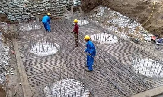
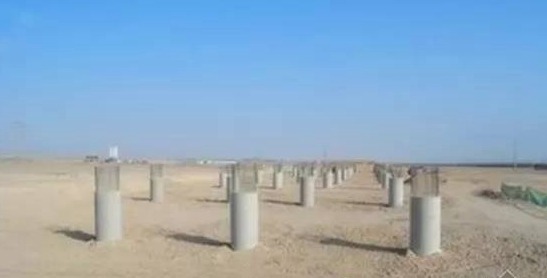
Bored cast-in-place piles have the advantages of low construction noise, and low vibration, pile length…
Bored cast-in-place piles have the advantages of low construction noise, and low vibration,…
The four major construction technologies are dry hole forming technology, slurry static pressure technology, casing…
Soil nail support is a new type of retaining structure developed in recent years for…
Pile Foundation Classification and Construction Principles 1. Classification According to Load-Bearing Piles ① Friction type…
Steel sheet pile cofferdams are suitable for basic projects such as sandy soil, gravel soil,…