Pile Foundation Classification and Construction Principles
1. Classification According to Load-Bearing Piles
① Friction type pile:
Friction pile: Under the limited state of bearing capacity, the vertical load on the pile top is borne by the pile side resistance, and the pile end resistance is so small that it can be ignored.
End-bearing friction pile: Under the limited state of bearing capacity, the vertical load on the pile top is mainly borne by the pile side resistance.
②End-bearing piles:
End-bearing pile: Under the limited state of bearing capacity, the vertical load on the pile top is borne by the pile end resistance, and the pile side resistance is so small that it can be ignored.
Friction end-bearing pile: Under the limited state of bearing capacity, the vertical load on the pile top is mainly borne by the pile end resistance.
2. Classification According to Pile Forming Method
① Non-squeezing soil piles: bored (digging) hole cast-in-place piles using the dry operation method, drilling (digging) hole cast-in-place piles using the mud wall protection method, and drilling (digging) hole cast-in-place piles using the casing wall protection method;
② Partially squeezed soil piles: punched cast-in-place piles, drilled squeeze-expanded cast-in-place piles, driven (static pressure) open steel pipe piles, open prestressed concrete hollow piles, and H-shaped steel piles.
③Squeezed soil piles: driven (static pressure) precast piles, closed prestressed concrete hollow piles, and closed steel pipe piles.
3. Classification According to Usage Functions
Pull-out piles, supporting piles, pressure-bearing piles, etc.
4. Construction Principles
The pile forming process should be based on the type of building structure, load properties, pile use function, soil layer crossing, pile end bearing layer, groundwater level, construction equipment conditions, construction environment, construction experience, pile-making material supply conditions, etc., and should be based on safe use. , Selection based on economic and reasonable principles.
Commonly Used Mechanical Equipment for Bored Piles
Commonly used construction machinery and equipment for bored piles include rotary drilling rigs, impact drilling rigs, rotary drilling rigs, truck cranes, mud pumps, excavators, electric welding machines, butt welding machines, etc.
1. Rotary drilling rig
The rotary drilling rig is a construction machine suitable for drilling operations in construction foundation projects. It is widely used in foundation construction projects such as municipal construction, highways and bridges, high-rise buildings, etc. It is suitable for dry (short spiral) or wet (rotary bucket) and rock formation (core drill) drilling operations with different drilling tools. The drilling rig has the characteristics of large installed power, large output torque, large axial pressure, flexible maneuverability, high construction efficiency, and multi-function. Rotary drilling rigs are adapted to the soil geological conditions in most areas of our country and have a wide range of uses. They can meet the needs of bridge construction, foundations of high-rise buildings, and other projects. At present, rotary drilling rigs have been widely used in various bored pile projects.
At present, most rotary drilling rigs in my country’s engineering industry are products from Germany and Italy and have occupied a dominant position.
Major domestic manufacturers include Xugong Machinery, Sunward Intelligent, Sany Heavy Industry, Zoomlion, etc.
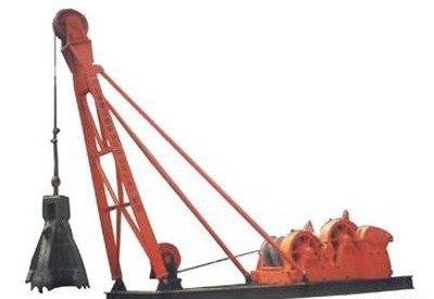
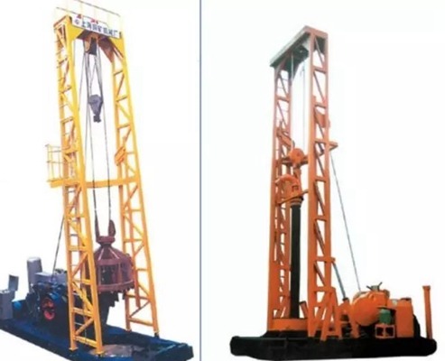
2. Commonly used impact drills
The vertical reciprocating motion of the drilling tool causes the drill bit to impact the bottom of the well to break the rock formation. Its structure is simple and there is no circulating well cleaning system. The removal of rock cuttings and the drilling rig cannot be carried out at the same time, so the efficiency is low. There are 2 main types:
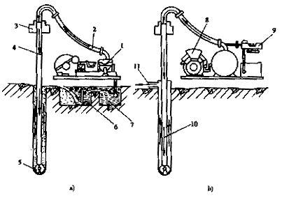
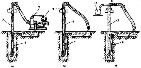
3. Commonly used rotary drilling rigs
The working principle of a positive circulation drilling rig (as shown in the figure below). The motor drives the turntable to drive the drill pipe and drill bit to rotate and drill. At the same time, the mud pump is started to apply pressure on the mud in the mud pool to pass through the hose, lifting faucet, and hollow drill pipe. Finally, it is sprayed out from both sides of the lower part of the drill bit to wash the bottom of the hole. And the drilling residue mixed with the mud rises along the hole wall, is discharged through the hole, and flows into the circulation tank. After the drilling residue is deposited, the cleaner mud flows back into the mud pool, thus forming a working cycle.
The working cycle of a reverse circulation drilling rig (as shown in the figure below). The working mud circulation of this type of drilling rig is opposite to the positive circulation direction. The mud with impurities enters the mud pump through the drill bit, hollow drill pipe, water lifting valve, and hose, and then is discharged from the gate valve of the pump and flows into the mud pool. The mud is then settled and then returned to the mud pool. Flow into the well.
4. Car Crane
Truck cranes are mainly used for hoisting steel cages, moving drilling rigs, lowering concrete ducts, and hoisting other materials; the selection is mainly based on the weight of the steel cage and the actual hoisting conditions on-site.
5. Mud Pump
6. Other Equipment
Excavators, electric welders, butt welders, etc.
Bored Cast-in-Place Pile Construction Technology
1. Construction Preparation
Bored cast-in-place piles are an underground hidden project with high-quality requirements, and many construction procedures, and need to be completed continuously in a short period. To ensure that construction proceeds in an orderly and fast-paced manner, technical preparations, site preparations, labor preparations, mechanical equipment preparations, and material preparations must be made carefully before the start of construction.
1) Technical preparation work
Joint review of drawings, measurement intersections, preparation and review of construction organization design, and technical disclosure;
Select construction methods and mechanical equipment based on geological data;
2) Preparation for on-site work
Site leveling, construction road planning and formation, steel processing site and transportation road formation, mud pool and mud ditch layout and implementation, waste slag yard layout and setup, water and electricity layout and formation.
2. Measurement and Positioning
The measurement control network is arranged according to the floor plan provided by the owner and the axis of each unit project.
Key parts such as measurement control points and elevation datum points handed over by the owner shall be protected and marked, and detailed written information shall be filed together.
The instruments used for pile position measurement and elevation measurement are total stations, levels, and tower rulers.
According to the measurement control network provided by the owner, a total station is used for measurement and placement. Before measuring and placing pile positions, the coordinates of each control point and pile position should be calculated based on the construction drawings and site coordinate system. After verification, the “Construction Pile Position Coordinate List” should be filled in for use when measuring and placing pile positions.
Construction is strictly prohibited on pile positions that have not been inspected and accepted.
(1) The casing is generally rolled from steel plates. The thickness of the steel plate should be 4 to 8 mm depending on the aperture size. The inner diameter of the casing should be larger than the pile diameter (larger than 200mm for rotary drilling rigs and larger than 400mm for impact drilling rigs). The upper part should be opened with 1 to 8 mm. 2 overflow holes.
(2) Under normal circumstances, the burial depth of the casing should not be less than lm in clayey soil; it should not be less than 1.5m in sandy soil; its height should still meet the requirements of the mud surface height in the hole. For soft soil layers such as silt, the burial depth of the casing should be increased; the top surface of the casing should be 500mm higher than the ground, and 2000mm higher than the construction water level and groundwater level.
(3) The casing can be dug and buried in dry land and island construction. The bottom and surrounding sides of the casing are backfilled with clay soil and compacted in layers. When setting up the casing in water areas, strict attention should be paid to the plane position and vertical inclination. The casing can be sunk The methods of weight pressing, vibration, hammering, and supplemented by taking soil from the casing are used.
(4) After the casing is buried, the vertical line in the center of the casing should coincide with the center of the pile. Unless otherwise specified in the design, the allowable error in the plane is 50mm, and the inclination of the vertical line should not be greater than 1%.
(5) The joint of the casing is required to have no protrusions in the cylinder, and it should be resistant to tension, and pressure, and watertight. The height and depth of the casing should be appropriately adjusted according to the fluctuation of groundwater level, and an impermeable layer should be driven into it if necessary.
4. Preparation of Wall Protection Mud
(1) Wall protection mud is generally prepared from water, clay (or bentonite), and additives in a certain proportion, and can be stirred evenly in mud pools and boreholes by machinery.
(2) The configuration of mud should be determined based on the engineering geology of the borehole, hole location, drilling rig performance, circulation method, etc.
5. Drilling Construction
(1) General requirements
(2) Hole forming with rotary drilling rig
(3) Hole forming with impact drill
(4) Precautions during drilling
6. Clear Holes
(1) The hole cleaning is carried out in two times. The drilling depth meets the design requirements. The hole depth, hole diameter, hole verticality, etc. are checked. After the requirements are met, the first hole cleaning is carried out; the steel frame and conduit are placed, and the concrete is poured. Before that, a second hole cleaning should be done.
(2) The first hole cleaning is carried out according to the design requirements, and the construction machinery uses methods such as slurry replacement, slurry pumping, mud suction, and slag removal. The second hole cleaning is carried out according to the hole diameter, hole depth, and design requirements. Positive circulation and pump suction are used. Reverse circulation, gas lift reverse circulation, and other methods are used.
(3) The sediment thickness and mud performance index after the second hole cleaning should meet the design requirements, and generally should meet the following requirements; sediment thickness for friction piles ≤ 300mm, end-bearing piles ≤ 50mm, friction end-bearing or end-bearing friction piles ≤ 100mm; Mud performance indicators before pouring concrete, the relative density within 500mm of the hole bottom is ≤ 1.25, the viscosity is ≤ 28s, and the sand content is ≤ 8%.
(4) No matter what hole cleaning method is used, when cleaning the hole and discharging slag, attention must be paid to maintaining the water head in the hole to prevent hole collapse.
7. Production and Installation of Steel Frame
(1) The production of steel frames should comply with the design and specification requirements.
(2) The long pile skeleton should be made in sections. The length of the sections should be calculated and determined based on the hoisting conditions and the total length. It should be ensured that the steel frame does not deform when moving and lifting. The joints of two adjacent sections of the steel frame should be staggered according to relevant specifications.
(3) Pads should be set outside the steel frame to control the thickness of the protective layer. Concrete pads with the same strength as the concrete of the pile body can be used or steel bars can be welded to the vertical main bars. The vertical spacing between them should be 2m, and the horizontal circumference should not be less. at 4 places and evenly arranged. The top of the frame should be provided with lifting rings.
(4) After the large-diameter steel frame is produced, cross braces or triangular braces should be installed on the internal reinforcing hoops to ensure that the steel frame does not deform during storage, movement, and hoisting.
(5) A crane is generally used to enter the skeleton hole. For small-diameter piles without a crane, a drilling rig, pouring tower, etc. can be used. Lifting should be carried out according to the number of the frame length. During the lifting process, measures should be taken to ensure that the frame does not deform.
(6) When transporting and hoisting, deformation should be prevented, and the placement should be aligned with the hole position to avoid collision with the hole wall. It should be fixed immediately after being in place. When the steel frame is hoisted into the hole, it should be centered to prevent collision with the hole wall. After the steel frame is hoisted into the hole, its position must comply with the design and specification requirements, and ensure that no displacement occurs during the process of placing the conduit, clearing the hole, and pouring concrete.
8. Concrete Pouring
(1) The concrete mixture supply capacity when pouring underwater concrete should ensure that the pile holes are filled within the specified time; the concrete pouring time shall not be longer than the initial setting time of the first batch of concrete.
(2) Concrete pumps or concrete mixer trucks should be used for concrete transportation; when the transportation distance is less than 200m, motorized dump trucks or other tools that are tight and solid, do not leak grout, do not absorb water, and are easy to load and unload can be used to ensure that the concrete does not segregate. , with good workability and liquidity.
(3) The pouring of underwater concrete is generally constructed using the steel conduit back-top method. The inner diameter of the conduit is 200~250mm, depending on the pile diameter, and the wall thickness is not less than 3mm; the diameter production deviation should not exceed 2mm; the conduit interfaces are For threaded or flange connections, a sealing ring or rubber pad must be added when connecting, and the threaded buckles or bolts must be tightened. Before using the conduit, a watertight pressure-bearing and joint tensile test should be carried out (the water test pressure is generally 0.6~1.0 MPa) to ensure the sealing of the conduit mouth. Before placing the conduit, the hole depth and total length of the conduit should be calculated. The length of the first section of conduit is generally 4 to 6m, and the standard section is generally 2 to 3m. 2 to 3 short sections of 0.5-1.0 m can be placed on the upper part. to adjust the total length of the catheter. When placing the conduit, ensure that the conduit is centered in the hole to prevent collision with the steel frame.
(4) Technical requirements for pouring underwater concrete
Construction Layout
The construction site must be leveled before the equipment enters the site; water and electricity must be connected, and access roads for construction vehicles must be paved; holes must be formed, poured, steel cages made, concrete materials, wastewater, and residue temporarily stored, materials and tools stored, and the construction site set up. Plan and arrange temporary facilities and other needs.
Since a large amount of waste sewage and mud-containing drilling slag will be produced during the construction process, if the management is not careful, water will flow everywhere, making the work site muddy, affecting the passage of personnel and vehicles and the movement of equipment and equipment, and polluting the construction materials and pollute the surrounding environment. Therefore, when preparing the work site, the possibility of muddy conditions must be considered. In addition to appropriately increasing the size and volume of the circulation system, multiple waste slurry drilling slag removal channels must be arranged. If necessary, gravel slag can be paved on the channels and fully compacted. Or spare steel plates, dig drainage ditches and ponds on both sides of the passage and other low-lying areas prone to water accumulation and carry out frequent dredging to prevent sewage from overflowing.
After the site is delivered by the requirements of “three connections and one leveling”, the overall arrangement and consideration of the site shall be carried out according to the general construction layout plan, the mud circulation system shall be reasonably arranged, and the materials shall be stacked in a reasonable, convenient and orderly manner, not only taking into account the convenience of material access but also taking care of It is convenient for construction operations.
Quality Standards and Control Points
1. The quality of construction machines and tools plays a vital role in ensuring construction quality. Choosing appropriate construction machines and tools is the prerequisite for achieving quality control.
2. When the pile driver is in place, it is first necessary to ensure that the engineering pile positions are accurate. To this end, in addition to comprehensively measuring and setting the engineering pile positions, the engineering pile positions should also be retested when the pile driver is in place, and different measuring stations should be used for review. , where possible, steel rulers should be used to conduct mutual verification of adjacent pile positions at the front, rear, left, and right. Pile position control during the construction of cast-in-place piles must be paid great attention. Once an error occurs, it will be difficult to make up for it.
3. The basic requirements for the pile driver to be in place are that the plane position is accurate, and the pile driver machine platform is level and stable. After installation, a spirit level and a measuring hammer must be used to verify. Due to the large vibration during the punching process, the pile driver’s often machine platform is not firmly padded and tilts and deviates. Therefore, during the punching process, it is necessary to regularly or irregularly check whether the wire rope coincides with the center of the pile position so that the verticality and pile position of the pile can be guaranteed.
4. Punching cast-in-place piles rely on mud to protect the wall to prevent hole collapse. Mud circulation is used to clean holes and remove slag. Mud-specific gravity and viscosity are the two most intuitive and important indicators. If the mud’s specific gravity is too small, it will be difficult to protect the wall and it is easy to collapse the hole; If the specific gravity of the mud is too large, it will affect the punching progress and the wall film will be too thick. Therefore, correctly controlling the specific gravity of the mud is an important part of smooth hole construction and ensuring quality. During the construction process of punched cast-in-place piles, the specific gravity of the mud adopts different values according to different soil layers to prevent hole expansion and hole collapse, thereby ensuring the quality of the project.
5. During the punching process, the mud circulation volume should be adjusted according to the formation and footage speed. If the footage velocity is fast and the circulation volume is small, the mud will be viscous and there will be a lot of mud and sediment, which will affect the hole-forming quality; in soft strata, if the circulation volume is large, it will cause diameter expansion or even hole collapse. When finalizing the hole, it is necessary to check the depth and diameter of the pile hole and whether it reaches the bearing layer. The hole can be finalized only if it meets the design and specification requirements.
6. Punching cast-in-place piles is a method of partially squeezing soil to form holes. The principle of jumping should be implemented to prevent the stress release caused by the pile driver load and punching from affecting the quality of the adjacent piles that have just poured concrete. When the avoidance cannot be adjusted, When starting, construction of adjacent piles should be carried out at least 72 hours after the concrete pouring is completed.
7. During the punching process, the mud circulation volume should be adjusted according to the formation and footage speed. If the footage velocity is fast and the circulation volume is small, the mud will be viscous and there will be a lot of mud and sediment, which will affect the hole-forming quality; in soft strata, if the circulation volume is large, it will cause diameter expansion or even hole collapse. When finalizing the hole, it is necessary to check the depth and diameter of the pile hole and whether it reaches the bearing layer. The hole can be finalized only if it meets the design and specification requirements.
8. Secondary hole cleaning is usually used to meet the technical performance requirements of the mud before concrete pouring.
The first hole cleaning is the mud circulation cleaning work performed when the hole is punched into the bearing layer and enters the bearing layer to reach the design depth requirement. The first hole cleaning is the basis for whether the technical requirements can be met. The importance of the first hole cleaning cannot be ignored because the second hole cleaning because first hole cleaning has strong suction and strong hole cleaning ability, and can completely Most of the sediment sucked out of the hole; the second hole cleaning is the steel cage and conduit are installed, and the conduit is used to clean the hole. The suction force is much smaller. The purpose is to remove the sediment that settled at the bottom of the hole or the conduit during the process of installing the steel cage and conduit. Mud debris fell after being hit by the steel cage. During the hole cleaning process, the water head in the hole must be maintained to prevent hole collapse.
9. The technical requirements for the production of steel cages are mainly:
The diameter of the steel cage should comply with the design size;
②The length of each section should not exceed 9 meters, nor should it be shorter than 5 meters, because if it is too long, it will easily bend and deform when hoisted, and if it is too short, it will increase the welding time, which is detrimental to the quality of the pile;
③ When using flange joint conduits, the stiffening hoop should be set outside the main bars. The main bars generally do not have hooks. The hooks set according to the process requirements must not extend inwards to prevent the conduit hooks from causing the steel cage to float up;
④ The finished steel cages should be stacked horizontally on a flat and clean site, and the stack height should not exceed two floors.
⑤ The steel cage should be hoisted section by section and the openings should be welded. The welding method of the main bars of the steel cage is vertical welding. The welding personnel are required to have a very high level of welding technology to ensure the welding quality.
⑥ The steel cage should be lowered as quickly as possible. Generally, the pile holes should be completed within 2-4 hours.
10. Requirements for underwater concrete pouring
First of all, the strength level of concrete must meet the design requirements. In addition, according to the characteristics of cast-in-place piles, underwater concrete also needs to be controlled:
① Initial setting time: This indicator is very important for cast-in-place piles. Generally, the initial setting time of the provided ratio is The actual watering time should be twice the actual watering time, otherwise, accidents such as condensation of the pipe may occur during the watering process.
②Good workability: The sand content should be 40-45, and medium-coarse sand should be used. The maximum particle size of coarse aggregate should be less than 40MM. If conditions permit, the secondary mix can be used, and the slump is required to be between 180-220MM. When the slump is small, it is easy to block the conduit, and when the slump is large, segregation is easy to occur.
The above technical requirements should be specified in the concrete supply contract.
① Before pouring underwater concrete, the sediment thickness and mud technical performance indicators at the bottom of the pile should be checked. If the requirements are not met, the hole should be cleaned again.
② When starting to pour concrete, to allow the water isolation plug to be discharged smoothly, the distance from the bottom of the conduit to the bottom of the hole should be 300-500MM, and there should be enough concrete reserve to allow the conduit to be buried in the concrete surface for more than 0.8M at a time. , when the concrete is poured into the hole and no more mud returns, it means that the concrete pressure is equal to or less than its resistance to lifting in the pile. At this time, the conduit should be raised; if it needs to be raised by more than 0.5-1.0M before concrete can be poured, then this time, some conduits should be removed to reduce the buried depth of the conduits in the concrete so that the power is greater than the resistance again.
③ The buried depth of the conduit should be 2-6M. It is disadvantageous if the buried depth of the conduit is too large or too small. If the buried depth is too deep, it will easily lead to pile breakage accidents in which the concrete solidifies the conduit. If the buried depth is too shallow, it will easily break the concrete roof in the hole. The sediment and mud will be involved in the surface, causing the mud to be trapped and the pile to be broken, and it is also easy to cause an accident by pulling out the conduit from the concrete. Therefore, demolition should be carried out frequently, and demolition of more than ten meters at a time should not occur.
④ Control the final pouring amount, the top of the pile must not be too low, and it must be ensured that the concrete on the top of the pile reaches the strength design value after removing the grouting height.
⑤ Underwater concrete must be constructed continuously. The pouring time of each pile is controlled according to the initial setting time of the initial concrete. Construction records must be kept and all failures during the pouring process must be recorded.
Post Management Responsibilities During Pile Foundation Construction
1. Technician management responsibilities
(1) Check the implementation of the construction plan during the construction process;
(2) Communicate with the foreman and quality inspector promptly during the construction process, and promptly communicate and resolve discovered design problems with the design institute.
2. Foreman’s management responsibilities
(1) The on-site foreman organizes construction personnel to inspect the burial of bored pile casings. The casing burial must meet relevant technical requirements;
(2) After the pile is drilled, the on-site foreman is responsible for filling in the drilling records truthfully.
(3) After the pile drilling is completed, the foreman first organizes the construction team to conduct a self-inspection and fill in the relevant acceptance form. After the self-inspection is passed, the quality inspector will conduct a re-inspection. After passing the self-inspection, the inspection form will be submitted to the supervisor for acceptance;
(4) Self-inspection content and requirements: ① The drilling depth should meet the design requirements, ② The mud index can only be lifted after all the mud indexes are qualified, and then the sediment thickness, borehole diameter, and verticality. The sediment thickness should be less than 20cm, and the drilling rig should be The diameter is not less than the designed pile diameter, and the verticality is less than 1%;
(5) After the pile hole is inspected and passed, the steel cage should be installed in time and should not be left in place for too long. When the pile hole is left in place for too long, the sediment thickness should be re-inspected;
(6) The production of steel cages should meet the design and specification requirements. The variety, specification, model, and quantity of steel bars must meet the design requirements. The thickness of the main bar protective layer should be 50mm;
(7) The pile steel cage should be hoisted into the hole as a whole immediately before concrete pouring. The steel cage should be ensured not to deform when hoisted, and the joints should be staggered according to regulations;
(8) After the construction of the steel cage is completed, the foreman first organizes the construction team to conduct a self-inspection and fill in the relevant acceptance form. After the self-inspection is passed, the quality inspector will conduct a re-inspection. After passing the inspection, the acceptance form will be submitted to the supervisor for acceptance. The production of the steel cage is allowed. The deviation is: main bar spacing ±10mm; stirrup spacing ±20mm; frame outer diameter ±10mm; frame verticality ±1%;
(9) After the steel cage is put down, check the center position and elevation of the steel cage. The center deviation is less than 2cm, and the cage top elevation deviation is less than +2cm;
(10) After the steel cage is put down, a conduit should be installed in time for secondary hole cleaning. The mud index of the secondary hole cleaning should meet the specification requirements. The mud discharged from the hole should be free of 2-3mm particles by hand. The specific gravity of the mud should not be greater than 1.1 and contain sand. The rate is <2%, the viscosity is 17-20s, and the pH value is >6.5. Concrete can only be poured when the thickness of the sediment at the bottom of the hole should be less than 20cm;
(11) When pouring concrete, the first pouring must ensure that the buried depth of the conduit is not less than 1m and not greater than 3m. During the pouring process, the buried depth of the conduit is not less than 1m and not greater than 3m. Strictly prevent broken piles during the construction process;
(12) The overgrouting height of the pile top shall not be less than 0.5m to ensure the strength of the concrete.
3. The management responsibilities of testers during the construction process
(1) Steel welded joints must be witnessed and sampled under the specifications, and the quality of the steel joints must comply with the specifications;
(2) All raw steel materials must be inspected and qualified to meet specification requirements;
(3) All raw materials used in concrete must pass the inspection and the quality must meet the specification requirements;
(4) During the concrete pouring process, the quality of the concrete should be checked, the slump of the concrete and the molding temperature of the concrete (the slump is 18-22cm, the molding temperature of the concrete is 5-35°C) and recorded;
(5) Each pile should be randomly sampled at the pouring site, and no less than one group of concrete test blocks should be made, and the supervision unit should witness the sampling or parallel sampling;
(6) Provide material inspection information to the foreman and quality inspector promptly, including copies of inspection reports for raw steel bars, welded joints, raw concrete materials, and concrete test blocks, to ensure that the materials used on site are qualified and the information is filled in correctly.
4. Management responsibilities of quality inspectors during pile foundation construction
(1) The quality inspector shall strictly follow the specifications and design requirements, supervise the entire pile foundation construction process management, review and sign various quality record forms such as inspection batches, inspection certificates, and quality control sheets, and submit them to the supervision company promptly;
(2) The quality inspector will supervise the pile foundation construction in strict accordance with the construction instructions to ensure that the construction proceeds normally and orderly;
(3) Report the issues raised by the supervision to relevant departments promptly, supervise the implementation of rectifications, and communicate well with the supervision unit;
(4) Each inspection batch shall promptly report to the supervision unit for inspection after passing the self-inspection, and organize the foreman and construction personnel to participate in the acceptance inspection;
(5) During the pile foundation construction process, if the quality inspector finds problems, he must send a written notice (rectification notice) to the foreman. After receiving the written notice, the foreman will complete the rectifications within the time specified in the notice and reply in writing.
Thank you!
Bored cast-in-place piles have the advantages of low construction noise, and low vibration, pile length…
Bored cast-in-place piles have the advantages of low construction noise, and low vibration,…
The four major construction technologies are dry hole forming technology, slurry static pressure technology, casing…
Soil nail support is a new type of retaining structure developed in recent years for…
Steel sheet pile cofferdams are suitable for basic projects such as sandy soil, gravel soil,…
The function of the pile is to transfer the load of the upper building to…