Pile pouring construction completed
The whole process of refined construction of prestressed bridges mainly includes seven aspects: pile foundation, pedestal, column, cap beam, precast slab, beam-slab, and bridge deck.
1.2 Construction methods, inspection standards, and quality control measures
1) Pile driver selection is based on the pile diameter and geological conditions in the design drawings. The pile driver is GPS15.
Measurement and layout are carried out according to the pile number in the design drawings, and the pile position is determined. The layout is measured and laid out using a total station. The supervisor engineer is on duty during the measurement. The measurement results should be recorded, and the data should be submitted to the supervisor engineer for review and signature.
The plane dimensions of the drilling site should be determined according to the plane dimensions of the pile foundation design, the number of drilling rigs and the plane dimensions of the drilling rig base, the requirements for the displacement of the drilling rig, the construction method, and the arrangement of other supporting construction machinery and facilities.
A. When the drilling site is on the ground, the site should be leveled, debris should be removed and compacted, and a simple working platform should be built.
B. The height of the water working platform should take into account the high water level that may occur during construction and be 0.5 to 1.0 m higher than the high water level. The spacing between wooden piles on the working platform is 1.5m (6m long, 16cm in diameter). They are arranged parallel to the center line of the bored piles with a center spacing of 1.5m. Square wood with a cross-section of 25×25cm2 is used as a guide in the longitudinal direction to fix the piles, and then horizontal guides are laid, and then two longitudinal guides are laid for the drilling rig to move.
Buried casing requires stability and accuracy, and more than 50cm into the hard soil.
Casing production requirements: strong, durable, not easy to deform, no water leakage, easy to load and unload, and reusable.
The inner diameter of the casing should be slightly larger than the design diameter of the bored pile. The casing adopts a steel casing with a flange, generally made of a 3-5mm thick steel plate. In order to increase rigidity and prevent deformation, a stiffening rib can be welded on the outer side of the upper, lower, and middle ends of the casing. It can be made into a whole or two semicircles.
The drill frame should be able to bear the weight of the drilling tool and other auxiliary equipment. At the same time, it should have good stability and a certain rigidity. It should not move or shake during drilling or other operations. Its height should be determined according to the length of the drilling tool and the length of the steel skeleton section, generally 8-12m.
When the drilling rig (frame) is installed in place, detailed measurements should be made, the base should be padded with sleepers, the top should be fixed and stabilized with a cable wind rope, and frequent checks should be made during the drilling process to ensure that the turntable surface is horizontal and the drilling rig frame is vertical to ensure the verticality and hole diameter of the pile body.
After the pile frame is in place and aligned with the center of the pile position, it needs to be reviewed by the supervision engineer.
During the drilling process, the hole should maintain a certain consistency of mud. When drilling in a good clay layer, clear water can also be poured in. When drilling, the hole is self-made mud to achieve a solid wall effect.
Inspection standards:
A. The center position deviation of the pile position measurement requires ≤5mm.
B. Requirements for buried casing: The plane position of the casing should be buried correctly, and the deviation should not be greater than 50mm. The top elevation of the casing should be 1.0~1.5m higher than the highest water level of construction.
C. The general specific gravity of the mud is preferably 1.15~1.2.
The sedimentation tank and water supply tank required for drilling should be set on the same side of the drainage outlet of the drilling rig. The distance from the drilling rig can be determined according to the terrain. The total volume of the two tanks is generally 1.2 to 2.0 times the total slag volume after the drilling is completed.
1) Drilling rig in place. Set up the drill frame and adjust and install the lifting system, lift the drill bit, and put it into the casing. Start the winch to lift the turntable, put square wood under the turntable base, level the drilling rig, and align it with the drill hole. Then install the turntable, requiring the center of the turntable to be on the same plumb line as the lifting pulley on the drill frame. The drill rod position deviation shall not exceed 2cm. The turntable should be checked frequently during the drilling process. If there is any tilt or displacement, it should be corrected in time.
Start the winch, lift the square drill rod through the turntable, and connect it to the drill bit. Install the square sleeve to clamp the square drill rod, and prepare for drilling.
2) Drilling. Before drilling, prepare mud with a specific gravity of 1.15-1.2 and put it into the mud pool and hole. Start the drilling rig and drill slowly. During the drilling process, check the mud specific gravity in time and control it between 1.2 and 1.3. Control the viscosity at 16-22 seconds. If it is inconsistent, adjust it in time. If it is found that the terrain and geology do not match the provided information, contact the drilling and design units in time.
3) Extend the drill rod. When a drill rod is drilled, stop the turntable first, and let the circulation system continue to work until the sediment at the bottom of the hole is drained (about 1-3 minutes), then turn off the mud pump and extend the drill rod. Pad a 3-5 mm thick rubber ring between the joint flanges and tighten the bolts to prevent air and water leakage, and then continue drilling as described above after everything is normal.
4) Control the drilling speed: When drilling in hard clay, use the first gear speed and loosen the lifting wire rope to advance freely. When drilling in ordinary clay and sandy clay, you can use the second or third gear speed and advance freely. When drilling in sand or a small amount of pebbles, it is advisable to use the first or second gear speed and control the advance to avoid sinking the drill bit or the speed of sucking the drilling slag cannot keep up.
When encountering silty sand with abundant groundwater and prone to collapse, it is advisable to drill at a low speed to reduce the stirring of the silty sand by the drill bit, and at the same time increase the mud density and water head to strengthen the wall protection and prevent the collapse of the hole.
1) Steel materials entering the site should have factory quality certificates and test reports. After entering the site, the certificate of conformity should be collected, and the supervision engineer should make test pieces for parallel testing.
2) Specific requirements for steel cage processing and production are as follows:
A. Before cutting steel bars, you should first be familiar with the design drawings and check the length and quantity of steel bars of various specifications. At the same time, ensure the number of steel bars required by the design.
B. The surface of the steel bar should be clean and undamaged. Before use, the surface oil stains, paint, skin, scale, rust, etc, It should be cleaned up. Steel bars with granular or flaky rust should not be used; after rust removal, if there are serious pits and spots on the surface of the steel bar, and the cross section has been damaged, it should be downgraded or removed.
C. The spacing of the reinforcement bars of the steel cage is 2m, and single-sided welding is adopted. The weld should be no less than 10d. It is located on the inner side of the main bar. The reinforcing stirrups should be welded to the main bar; the spiral bars are on the outer side of the main bar.
D. The pitch of the spiral reinforcement is increased to 10cm within 10m of the pile top, and 20cm for the rest.
E. The main reinforcement of the steel cage is mechanically connected, and the joints are upset straight threaded joints. The connection joints of the force-bearing reinforcement should be set at the place with the smaller internal force and should be staggered.
F. To ensure the thickness of the steel protection layer, the steel protection layer pads use round pancake roller mortar pads. One group is set every 2m, and each group of 4 is evenly set around the pile foundation reinforcement.
G. Each pile is arranged with an acoustic detection tube on the inner side of the pile body reinforcement according to the pile diameter equilateral triangle (three roots), and the acoustic detection tube is tied to the steel cage with iron wire. The two ends are closed with steel plates to prevent mud, debris, etc., from blocking the pipeline.
H. Appropriate measures should be taken to prevent the steel skeleton from deformation during transportation.
A. The reinforcement bars and main bars of the steel cage are all spot welded, and the spiral bars are tied to the main bars; the welding length and quality of the main bars meet the design and specification requirements, and the joints are staggered. Rust, oil stains, mortar, and other attachments on the steel bars should be completely removed to avoid affecting their effect on the concrete.
(4) Hole cleaning
After the final hole inspection, the hole should be cleaned quickly without stopping for too long, which will increase the sedimentation of mud and drilling debris, making the hole cleaning difficult or even causing the hole to collapse. Concrete should be poured in the shortest possible time after the hole is cleaned. According to the drilling method, when drilling with a positive circulation rotary drill, the drilling footage can be stopped after the final hole is completed, and the mud pump of the drilling rig’s circulation system can be used to continuously clean the hole debris for about 30 minutes.
After the hole is cleaned, the supervising engineer will review the sediment thickness.
Inspection standard:
The thickness of the bottom sediment of the hole shall not exceed 0.3d.
(5) Installing and hoisting the steel cage
When the mud density is 1.15-1.18, the steel cage shall be placed.
1) The steel bars of the bored pile shall be pre-welded into the steel cage frame according to the design requirements, and then hoisted into the drill hole in sections.
2) Before hoisting the steel cage frame, check whether the bottom depth of the hole meets the requirements and whether there are any obstacles to the hoisting and correct positioning of the frame on the hole wall. The steel cage can only be placed after the above conditions have been accepted by the supervision engineer.
3) The steel cage shall not be deformed during transportation and hoisting. The steel cage can be hoisted by the drilling rig tower. To ensure that the frame does not deform during hoisting, it is advisable to use two-point hoisting. The first hoisting point is set at the bottom of the frame, and the second hoisting point is set between the midpoint of the frame length and the upper three points. Then hoist until the frame is perpendicular to the ground and stop hoisting. Release the first hoisting point and check whether the frame is straight. If it is bent, it should be straightened.
When the skeleton enters the hole, it should be straightened and lowered. It is strictly forbidden to swing and collide with the hollow wall. When the skeleton descends to the second lifting point and the reinforcing hoop is close to the hole, a wooden stick or a steel chisel (depending on the weight of the skeleton) can be used to pass through the bottom of the reinforcing hoop to temporarily support the skeleton at the hole. Move the hook to the upper end of the skeleton, remove the temporary support, and continue to descend to the reinforcing hoop behind the skeleton. Temporarily support it according to the above method. At this time, the second section of the skeleton can be hoisted so that the upper and lower sections of the skeleton are located on the same vertical line for welding. After the last joint is welded, all joints can sink into the water. After the joint is completed, lift the skeleton slightly, remove the temporary support, and slowly lower the skeleton. Repeat this cycle until the skeleton is lowered to the designed elevation. Finally, use four lead wires to tie the skeleton to the chassis of the drill frame or the cross frame temporarily set at the hole, and then loosen the skeleton’s hanging point.
Inspection standard: Measure whether the elevation of the steel skeleton is consistent with the design elevation. The deviation shall not exceed ±5cm.
(5) After the second cleaning is completed, the hole is cleaned again through the conduit. When the mud density is about 1.15, the sedimentation is ≤10cm, and the hole diameter and hole depth meet the design requirements, the concrete pouring is reported to the supervisor for approval.
(6) Pouring underwater concrete. The vertical rise conduit method is used to pour underwater concrete.
1) Preparation work
The conduit is pre-assembled in sections beside the borehole, and then assembled section by section when it is hoisted. When the conduit is hoisted, it should be placed in the center of the hole, with a straight axis, and sunk steadily to prevent the steel bar skeleton from getting stuck and colliding with the hole wall.
A funnel should be set on the top of the conduit, and a chute, a storage hopper, and a working platform should be set above it. In addition to meeting the needs of operations such as conduit disassembly, the height of the storage hopper and the funnel should also meet the needs of the height of the concrete column in the conduit when pouring to the final stage.
After completing the above preparation work, according to the construction requirements, lay the ramp, prepare various raw materials such as concrete mixing equipment, sand, gravel, cement, etc., prepare to mix concrete, and pour bored piles.
2) Pouring of underwater concrete
A. Pouring underwater concrete is an important process in bored pile construction and should be paid special attention to. The drilling should be qualified after the hole quality inspection before pouring.
B. Before pouring, the thickness of the sediment layer at the bottom of the hole should be measured again. If the thickness exceeds the specified value, the bottom of the hole can be sprayed for 3 to 5 minutes by jetting to suspend the sediment, and then the first batch of concrete can be poured immediately.
C. After the ball is cut, the bolt is pulled or the valve is opened, and the first batch of concrete is poured into the bottom of the hole, the height of the concrete surface in the hole is immediately measured to calculate the buried depth of the conduit. If it meets the requirements, it can be poured normally. If a large amount of water is found in the conduit, it indicates that a pouring accident has occurred, which should be handled according to the accident handling method.
D. After the pouring starts, it should be carried out compactly and continuously, and it is strictly forbidden to stop work in the middle.
When the conduit is lifted, keep the axis vertical and the position centered, and lift it gradually. If the conduit flange is stuck on the steel frame, the conduit can be rotated to disengage the steel frame and move it to the center of the drill hole.
When the conduit is lifted to a certain height above the exposed hole of the flange joint, the 1st and 2nd sections of the conduit can be removed (depending on the length of each section of the conduit and the height of the working platform from the hole). At this time, suspend the pouring, first remove the funnel, re-tie the conduit at the wellhead, and hang the lifting equipment, then loosen the joint bolts or quick connectors of the conduit, and at the same time hang the hook used to lift the conduit on the lifting ring at the upper end of the conduit to be removed. After all the bolts are removed or the quick connector is removed, lift the conduit to be removed, slowly put it on the ground, and then reinsert the funnel into the conduit at the wellhead, correct the position, and continue pouring.
The conduit removal action should be fast, and the time should generally not exceed 15 minutes. Prevent bolts, rubber pads, and tools from falling into the hole, and pay attention to safety. The removed pipe sections should be cleaned immediately and stacked neatly.
E. During the pouring process, when the concrete in the conduit is not full and contains air, the subsequent concrete should be poured slowly, and the funnel and conduit should not be poured into the whole bucket, so as to avoid the formation of high-pressure air bags in the conduit, squeezing out the rubber pads between the pipe sections, and causing the conduit to leak.
F. When the concrete surface rises to the lower end of the steel skeleton, the following measures can be taken to prevent the steel frame from being lifted by the concrete:
Try to shorten the total pouring time of concrete to prevent the top concrete from entering the steel skeleton. The fluidity of the concrete is too low. It is recommended to use a retarder.
When the concrete surface approaches and initially enters the steel skeleton, the pipe should be buried deeper, and the concrete should be poured in slowly to reduce the upward impact force of the concrete after it comes out of the bottom of the conduit.
When the concrete surface in the hole enters the steel skeleton 1 to 2m, the conduit should be appropriately lifted and the buried depth of the conduit should be reduced (not less than 1m) to increase the buried depth of the skeleton below the bottom of the conduit, thereby increasing the bond strength of the concrete to the steel skeleton.
G. To ensure the quality of the pile top, a certain height should be poured above the designed elevation of the pile top so that this section of concrete can be removed after the pouring is completed. The increased height can be determined according to the hole depth, hole forming method, and hole cleaning method. Generally, it should not be less than 0.5m, and deep piles should not be less than 1.0m.
To reduce the workload of chiseling out the pile head later, an excess section of the pile head can be dug out after the pouring is completed and before the concrete solidifies, but 10 to 20 cm should be retained for subsequent chiseling and pouring of the foundation.
H. When pouring is almost finished, the height of the concrete column in the conduit decreases, the pressure decreases, and the mud and the slag contained in the conduit increase in consistency and specific gravity. If it is difficult to lift the concrete, water can be added to the hole to dilute the mud, and some of the sediment can be removed to make the pouring work go smoothly. When removing the last section of the long conduit, the pulling speed should be slow to prevent the mud settled on the top of the pile from squeezing under the conduit to form a mud core.
I When pouring concrete, each pile should be made of no less than 1 group (3 blocks) of concrete test blocks, and 2 groups of test blocks should be made. The test blocks should be properly protected, and after the strength test, they should be filled in the test report form. When the strength does not meet the requirements, a report should be submitted in time for remedial treatment.
J. Regarding the concrete pouring situation, each pouring time, the depth of the concrete surface, the buried depth of the conduit, the removal of the conduit, and the abnormal phenomena that occurred, etc., a designated person should be designated to record.
Inspection standards:
After the pile head is chiseled, it should be reported to the supervisor for acceptance, and the concrete cushion layer can be poured only after passing various tests, such as ultrasonic testing. All pile foundations must undergo ultrasonic or small-strain testing, and the large-strain testing ratio is based on the requirements of the design drawings. The test results require that Class I piles be≥ 95%, and there are no Class III piles.
(1) Measures to prevent necking: The key to preventing necking is to control the specific gravity of the mud and ensure that the mud can maintain the balance of the hole wall.
1) Use a drill bit with a suitable diameter to drill holes, and use different muds according to the changes in the strata.
2) When drilling holes, attention should be paid to hole cleaning. When cleaning the holes, the slag should be cleaned but not the mud to prevent local collapse during the pouring of concrete after cleaning, which will lead to necking.
3) When drilling holes, the pump volume should be increased, the drilling speed should be accelerated, and the hole should be passed quickly. After a period of drilling, a mud skin will form on the hole wall, and the hole wall will not seep water or cause expansion. If necking occurs, the hole should be repeatedly swept up and down to expand the hole diameter.
2) Prevention and control measures for bottom sedimentation:
If the hole does not meet the requirements after the first cleaning, measures should be taken, such as improving the mud performance and extending the cleaning time. After the steel cage is lowered, check the sediment volume. If the sediment volume exceeds the specification requirements, the hole should be cleaned again. The second cleaning can be carried out using a guide tube. After the sediment thickness reaches the design and specification requirements, underwater concrete pouring should be carried out as soon as possible.
(3) Prevention and control measures for hole collapse:
1) Use mud wall protection during construction.
2) It is forbidden to pile heavy objects near the hole or cause vibration caused by large machinery. When multiple pile drivers are arranged to work at the same time, they should be skipped.
3) If the above method is used, the hole collapse should not stop, or if the collapsed hole is deep, it is advisable to pull out the guide tube and steel cage, backfill with clay, and re-drill the hole.
(4) Floating steel cage
Prevention and control measures:
1) After the steel cage is hoisted, the upper end of the steel skeleton should be connected and fixed to the casing at the hole mouth in time. During the pouring of concrete, the concrete pouring elevation and the buried depth of the conduit should be kept at all times. When the concrete surface is close to the bottom of the steel cage, the concrete pouring speed should be slowed down, and the conduit should be kept buried at a large depth, so that the bottom of the conduit and the bottom of the steel cage are kept at a large distance to reduce the impact on the steel cage. When the concrete is buried 2 to 3 meters above the bottom of the steel cage, the conduit should be lifted above the bottom of the steel cage in time, but it should be noted that the conduit buried in the concrete surface should be no less than 2 meters and no more than 6 meters.
2) When it is found that the steel cage begins to float, the on-site operator should stop pouring immediately, accurately calculate the buried depth of the conduit and the elevation of the poured concrete, and immediately pull out and remove part of the conduit. After part of the conduit is removed, the conduit can be moved up and down appropriately. Each time the conduit is lifted, the steel cage will naturally fall back a little under the suction of the conduit. Keep moving the conduit up and down several times until all the floating steel cages fall back.
(5) Broken piles and mud layers
Prevention and control measures:
1) Carefully clean the hole to prevent the hole wall from collapsing. The conduit must have sufficient tensile strength to withstand its weight and the weight of the concrete. The inner diameter should be consistent, and the error should be less than ±2 mm. The inner wall must be smooth and unobstructed. After assembly, it must be tested with a ball plug and a check hammer.
2) Increase the concrete pouring speed as much as possible. When pouring concrete, try to accumulate a large amount of concrete to generate a great impact force to overcome the mud resistance; pour quickly and continuously to keep the concrete and mud flowing, which can prevent the conduit from being blocked.
3) Strictly control the buried depth and extraction speed of the conduit. The buried depth of the conduit in the concrete surface should generally be kept at 2 m- 4 m, not more than 6m or less than 1m. Measure the concrete pouring depth in time, and it is strictly forbidden to lift the bottom of the conduit out of the concrete surface. The lifting guide tube must be accurate and reliable. During the pouring of concrete, the buried depth of the guide tube should be measured at any time, and the operating procedures should be strictly followed. During the construction process, the pouring process and operation should be controlled well. The force of pulling the guide tube to raise the concrete surface should be moderate to ensure the procedure of pulling the guide tube and continuous pouring. The lifting and lowering amplitude should not be too large. If the guide tube is pulled out by a large amplitude, it is easy to cause the concrete body to scour the hole wall, causing the hole wall to fall or collapse, and the pile body to be trapped in mud. This phenomenon is particularly prone to occur in places with thick sand layers.
4) Before pouring underwater concrete, check whether the guide tube has leaks, bends, and other defects. If problems are found, replace it in time.
5) Regularly check the concrete mixture to ensure that it meets the requirements.
(6) Water seeps from the top of the pile andfrom holes in the pile body
Preventive measures:
1) Control the buried depth of the conduit and pull it out frequently during the pouring process.
2) The speed of pouring concrete into the conduit should be controlled according to the depth of the concrete in the conduit. The deeper the depth in the conduit, the slower the speed of pouring concrete should be. Whenever possible, the conduit should always be filled with concrete to prevent the formation of high-pressure air pockets in the pile body. In actual construction, it is often difficult to avoid the formation of high-pressure air pockets in the pile body when pouring again because the conduit will form an empty tube each time it is pulled out. Therefore, the conduit should be moved up and down appropriately during the pouring process to lead the formed high-pressure air pockets out of the pile body.
(3) Add an appropriate retarder to ensure that the underwater pouring is completed before the initial setting of the concrete.
7) Low concrete strength in the upper part of the pile
Preventive measures:
1) According to the pile diameter and the concentration at the bottom of the pile, the volume of the first bucket of concrete should be correctly determined. Generally, it can be 1.5- 2.0 m3. It can also be controlled at 10% of the designed volume of the pile body, or the over-pouring volume should be controlled. The pouring should not be stopped until all the floating slurry on the pile top overflows.
2) The quality of the pile is related to the pouring height of the pile body. Generally, the pile height is controlled to be 0.5-1.0m higher than the designed pile top elevation. After the concrete of the raised part is chiseled off, there should be no floating slurry and mud in the remaining part. The concrete grade should meet the design requirements, otherwise, it will be necessary to rework and re-pour.
1.4 Focus of refined construction Control measures
(1) Measures for handling obstacles.Since the bridge pile base of the Zhongshan Road renovation project is close to the old bridge, there may be a riprap backfill section or the original pile position may be encountered. Refined measures:
1) Investigate the original bridge design drawings and make judgments based on the on-site investigation.
2) Clean the river channel riprap backfill section after the cofferdam, use clay backfill after cleaning, and bury the steel casing.
3) If the new pile position hits the original pine pile reinforcement position, use excavation to remove it;
4) If the new bridge pile position conflicts with the old bridge pile position, make design adjustments, or adjust the construction process after obtaining the consent of the construction unit, supervision unit, and design unit, and use the punching method to drill holes;
5) If the new bridge pile encounters the existing or abandoned rainwater outlet, use an extended steel casing, and ensure that the steel casing exceeds the outlet bottom elevation by 1m when buried.
(2) Quality control measures for steel cage construction
The quality control of steel cage production is critical to the quality of bored piles, which is mainly reflected in the ingredients, size, protective layer pads, and welding process of the steel cage.
Refined measures:
1) The reinforcement forming method is used for steel cage welding every 2 meters or so. The reinforcement is set on the inside of the main reinforcement and reinforced with a triangular inner support. The main reinforcement is spot welded on the outside of the reinforcement. The main reinforcement and the reinforcement must be perpendicular, and then the stirrups are tied. The welding length of the main reinforcement is 10D (double-sided welding). To ensure the quality, the length is increased by 1 cm, and the joint position is staggered.
2) In addition to the normal setting of the steel cage protective layer, during the construction process, the steel cage should be vertically aligned with the center of the hole and then slowly lowered to prevent the “︺” reinforcement (also known as the steel ear) from scratching the hole wall. At the same time, during the hoisting process of the steel cage, when installing the mortar prefabricated circular pad, pay attention to the longitudinal consistency of the round steel bar and the longitudinal consistency of the skeleton. The pad can roll when the skeleton is lowered, and the number and distribution are moderate.
3) When preparing the steel cage, sufficient steel bars that penetrate deep into the foundation should be considered.
(3) Pile position accuracy control
1) The measurement work ensures that the pile position is measured before the casing is buried, and the pile position is checked after the casing is buried and positioned using the cross-wire method. The pile position is checked again before drilling.
2) Two groups of people are used to perform cross-measurement to ensure the accuracy of the measurement work.
(4) Concrete pouring height
1) When the concrete pouring is about to end, slow down the pouring speed, accurately calculate the burial depth, and pull the catheter up and down from time to time to make the concrete fall slowly.
2) In order to ensure the quality of the pile head, the over-pouring must be greater than 1.5m.
3) When the concrete pouring is completed, the catheter should be pulled out slowly. If it is pulled out too quickly, the concrete will be loose or hollow, affecting the quality of the concrete.
II. Fine Construction of Abutments and Bridge Pit
2.2 Construction Methods, Inspection Standards, and Quality Control Measures
(1) Excavation of Foundation Pit. Excavation of the foundation pit is carried out after the concrete of the pile body reaches a certain strength. Set up longitudinal and transverse intercepting ditches 5m outside the excavation line of the foundation pit to drain the surface water into the natural ditch. The drainage of the foundation pit adopts the method of setting up drainage ditches and water collection pits around the foundation pit, and a special person is responsible for removing the accumulated water in the foundation pit. It is strictly forbidden to soak the foundation pit with accumulated water.
Use excavators to excavate the slope, and reserve 30cm for manual bottom cleaning at the bottom of the pit. And according to the geological conditions, set up temporary support measures such as wooden piles or steel pipe piles to prevent slope collapse.
(2) Chiseling of pile heads and pile foundation inspection
Before breaking the pile head, the elevation line should be marked with red paint on the side of the pile body to prevent the pile head from being chiseled too much, resulting in the pile top extending into the abutment insufficiently. When breaking the pile head, an air compressor combined with manual chiseling should be used. The upper part should be chiseled by an air compressor, and the lower part should be chiseled 10 to 20 cm by hand. During the chiseling process, ensure that the pile body concrete below the designed pile top is not disturbed. It is strictly forbidden to use an excavator or a forklift to forcibly pull off the pile head to avoid damaging the main reinforcement. Clean and repair the pile body reinforcement extending into the pedestal into the designed shape, re-measure the pile top elevation, and conduct a pile foundation inspection.
After the pile head is chiseled, it should be reported to the supervisor for acceptance, and the concrete cushion layer can be poured only after passing various tests, such as ultrasonic waves.
(3) Rebar binding
After the pedestal foundation pit is excavated to the designed base elevation and passes the inspection, the foundation cushion layer concrete is immediately poured. Rebar binding should be carried out after the cushion layer concrete reaches 75% of the designed strength. Pop out the outer contour of the steel bar on the cushion layer surface, and mark the plane position of each steel bar with paint. The foundation cap steel bars are processed centrally and tied on site. The bottom foundation cap steel mesh is welded firmly to the pile body steel bars. The steel pipe rack is set up for tying and fixing the upper foundation cap steel bars and the pier body steel bars embedded in the foundation cap.
(4) Formwork installation
Large steel formwork should be used for the foundation formwork, and a crane should be used for installation. Composite steel formwork can also be used, supported by plywood. The formwork is erected after the reinforcement skeleton is tied. The wire method is used to straighten it, and the hanging ball method is used to control its verticality. The reinforcement is made by compacting and supporting the pit walls around the foundation pit with steel sections, square timbers, tie rods, and ensuring that the formwork is stable and firm and the size is accurate. The pier body embedded steel bars are tied after the model is erected. The accuracy is controlled according to the size of the upper mouth of the model. It is welded with the foundation steel bars to form an integral skeleton to prevent displacement.
(5) Concrete pouring
The concrete is commercial concrete, transported by tank trucks, pumped concrete, and vibrated by insert vibrators.
The average temperature of the concrete pouring environment is not less than 5℃, or the minimum temperature is not less than 3℃ during the day and night, and the local temperature is not higher than +40℃. Otherwise, corresponding cold prevention or cooling measures approved by the supervising engineer shall be adopted. When the upper layer of concrete is poured before the lower layer of concrete begins to set or can be reshaped, and the height difference of the concrete drop is greater than 2.0m, a string tube or chute is installed.
The concrete is poured in layers, and the layer thickness is controlled at 30-45cm. The vibrator is inserted for vibration, and it is strictly forbidden to collide with the steel bars and models during vibration. The vibration depth of the vibrator generally does not exceed 2/3-3/4 times the length of the rod. When vibrating, insert quickly and pull out slowly, and move the vibrating rod up and down continuously to ensure uniform compaction and reduce bubbles on the surface of the concrete. The vibrating rod is inserted into the lower layer of concrete for 5-10cm, and the moving interval does not exceed 40cm. Keep a distance of 5-10cm from the side mold. For each vibrating part, vibrate until the concrete at that part is dense, that is, the concrete no longer emits bubbles, and the surface appears flat and slurry.
(6) Backfilling ofthe foundation pit
After the concrete reaches the designed strength, the foundation pit is backfilled. In the collapsible area, the bridge pier foundation is backfilled with 3:7 lime soil, as shown in the figure below. The backfill is carried out simultaneously around the foundation pit. The backfill soil is backfilled in layers, with a thickness of 10 to 20 cm per layer, and compacted with a tamping machine.
(7) Curing
After the concrete is poured and initially set, it is watered and cured to ensure that the concrete surface is always moist. The curing period should meet the requirements of the specifications. Cover the concrete surface with a plastic film that can keep it moist or other materials that can keep it moist. The curing water and materials should not cause adverse effects on the appearance quality of the concrete.
2.3 Common quality problems and preventive measures
(1) The pile head is too short: The pile head does not meet the requirement of 10 cm deep into the foundation. Preventive measures: Keep the pile head about 30 cm and chisel out the pile head for the second time.
(2) The pile head steel bars are contaminated by concrete, and the steel bars are bent: Treatment measures: Avoid collision with the steel bars when chiseling the pile head, and use steel bar clips to straighten the bent steel bars; use a wire brush to clean the steel bars contaminated by concrete.
(3) The width and strength of the cushion layer concrete are not enough: Preventive measures: The cushion layer concrete is 50 cm wider than the foundation. If the bottom of the foundation pit is a plastic soil, some stone chips, crushed test blocks, or concrete after the pile head is chiseled out can be thrown down to squeeze the silt, and then high-grade concrete can be used to cast the cushion layer.
(4) There is no protective layer for the steel bars at the pile head: Preventive measures: When chiseling the pile head, adopt the first solution and chisel it out for the second time until it is close to the design elevation, chisel it from bottom to top, or use a hairpin to chisel it out manually.
(5) The pile head concrete is loose and the surface is not clean: Preventive measures: After the pile head is chiseled, it is manually leveled and washed with clean water.
(6) The foundation pit is soaked in water: Drainage ditches are made on the four sides of the foundation pit, and a water collection well is made at the same time, and water is pumped out by a water pump.
(7) The grounding steel bar welding does not meet the design requirements: Preventive measures: Fixed responsible personnel to perform welding, and establish reward and punishment measures.
(8) The concrete is not vibrated densely: Preventive measures: Increase the number of vibrators, divide the vibrators into different tasks, and vibrate at specified locations.
(9) The surface of the foundation is cracked: Preventive measures: The surface of the foundation is finished 2 to 3 times after pouring, that is, it is finished once after pouring, and twice after initial setting but before final setting. After final setting, it is covered and maintained in time, and the foundation pit is backfilled in time after the foundation formwork is removed.
2.4 Key control measures for refined construction
For the quality control of the joints of the foundation formwork and the tension screws, see the control of the joints of the cap beam and the column.
(1) Formwork control measures. The foundation formwork adopts a combined standard steel formwork, and the area of a single formwork shall not be less than 1 square meter. The specific assembly size depends on the side size of the foundation or the expanded foundation. The formwork with deformation shall not be used. The square wood or steel pipe behind the formwork shall have good strength, rigidity, and stability. Apply high-quality formwork oil.
The joints with misalignment must be polished. When removing rust, the formwork must be removed by mortar plastering and polishing with a polishing machine.
2.3 Common quality problems and preventive measures
(1) The pile head is too short: The pile head does not meet the requirement of 10 cm deep into the foundation. Preventive measures: Keep the pile head about 30 cm and chisel out the pile head for the second time.
(2) The pile head steel bars are contaminated by concrete, and the steel bars are bent: Treatment measures: Avoid collision with the steel bars when chiseling the pile head, and use steel bar clips to straighten the bent steel bars; use a wire brush to clean the steel bars contaminated by concrete.
(3) The width and strength of the cushion layer concrete are not enough: Preventive measures: The cushion layer concrete is 50 cm wider than the foundation. If the bottom of the foundation pit is a plastic soil, some stone chips, crushed test blocks, or concrete after the pile head is chiseled out can be thrown down to squeeze the silt, and then high-grade concrete can be used to cast the cushion layer.
(4) There is no protective layer for the steel bars at the pile head: Preventive measures: When chiseling the pile head, adopt the first solution and chisel it out for the second time until it is close to the design elevation, chisel it from bottom to top, or use a hairpin to chisel it out manually.
(5) The pile head concrete is loose and the surface is not clean: Preventive measures: After the pile head is chiseled, it is manually leveled and washed with clean water.
(6) The foundation pit is soaked in water: Drainage ditches are made on the four sides of the foundation pit, and a water collection well is made at the same time, and water is pumped out by a water pump.
(7) The grounding steel bar welding does not meet the design requirements: Preventive measures: Fixed responsible personnel to perform welding, and establish reward and punishment measures.
(8) The concrete is not vibrated densely: Preventive measures: Increase the number of vibrators, and divide the vibrators into different tasks, and vibrate at specified locations.
(9) The surface of the foundation is cracked: Preventive measures: The surface of the foundation is finished 2 to 3 times after pouring, that is, it is finished once after pouring, and twice after initial setting but before final setting. After final setting, it is covered and maintained in time, and the foundation pit is backfilled in time after the foundation formwork is removed.
2.4 Key control measures for refined construction
For the quality control of the joints of the foundation formwork and the tension screws, see the control of the joints of the cap beam and the column.
(1) Formwork control measures. The foundation formwork adopts a combined standard steel formwork, and the area of a single formwork shall not be less than 1 square meter. The specific assembly size depends on the side size of the foundation or the expanded foundation. The formwork shall not be used if it is deformed. The square wood or steel pipe behind the formwork shall have good strength, rigidity, and stability. Apply high-quality formwork oil.
The places where the joints are misaligned must be polished. When removing rust, the formwork must be removed by mortar plastering and polishing with a polishing machine.
2) Control of the phenomena of pockmarks, bubbles, exposed steel bars, etc., on the foundation
1) When vibrating with an inserted vibrator, keep a distance of 5-10cm from the formwork. The vibrator should avoid colliding with steel bars and formwork, and should not be placed on steel bars. Vibrate layer by layer without missing any vibrations to avoid honeycombs, pockmarks, and bubbles, and to avoid the formation of joints.
2) During the concrete pouring process, a dedicated person shall be assigned to supervise the formwork and check the stress of the formwork at any time. If the deformation of the formwork is found to exceed the allowable deviation, it shall be corrected in time before pouring can continue.
3) Concrete pouring shall be completed in one go, with an interval of no more than the initial setting time of the concrete, so as to eliminate the appearance quality defects of obvious stratification and uneven color of the concrete.
(3) Foundation pit enclosure and drainage
1) Ensure smooth drainage of the foundation pit, and do not allow the bottom of the pit to be soaked by rainwater.
2) Measures shall be taken for foundation pit drainage to protect the environment from pollution.
3) When the excavation depth exceeds 1.5m, ramps or ladders shall be provided for personnel to go up and down to avoid falling. Two 1.2m~1.5m high guardrails shall be provided at the edge to prevent falling accidents. Red signal lights shall be provided at night in dangerous places.
(4) Pipelines or water outlets are encountered during the excavation of the abutment
1) Make drawings and conduct on-site surveys before excavating the abutment;
2) If any problems are found, adjust the pipeline elevation or pipeline plane position in advance.
Construction methods, inspection standards, and quality control measures
(1) Measurement and layout. According to the requirements of the design and construction drawings, the center axis of the column and the elevation of the pile top are determined, and the cross line of the top and the control pile are laid out. The project is reported to the supervisor for review and acceptance. The mileage and coordinate dual control are used during the layout.
(2) Column reinforcement
1) The reinforcement processing and production are strictly carried out by the design drawings. The main reinforcement is connected by electroslag pressure welding or flash butt welding, and the main reinforcement joints in the same section do not exceed 25% of the total number of joints; to ensure the smooth discharge of concrete and the vibration of the operator, the horizontal branch reinforcement in the column is constructed by the method of pouring concrete while tying.
2) After the skeleton is formed, ensure that the cross-sectional dimensions are accurate and the thickness of the protective layer meets the design requirements. The skeleton dimensions must not be too large to prevent difficulties in template installation. After the reinforcement is tied and formed, please ask the supervisor to check and install the template after approval.
3) Before use, the column reinforcement is fully inspected. If it is unqualified, it is strictly forbidden to proceed to the next process.
3) Column formwork
To ensure that the appearance of the column is smooth, flat, and straight, the formwork of the column should adopt a standardized composite steel formwork. The specifications and quantity of the formwork are determined according to the size of the pier, the progress requirements, and the number of turnovers to determine the corresponding number of integral column formworks.
1) Formwork production.n The key to the production of the formwork is to control the rigidity, straightness, and verticality of the steel formwork. The steel formwork is made by a professional steel component factory. During the production, a special person is assigned to supervise the quality to ensure the material and joint density of the formwork.
2) Formwork installation. The installation of the formwork adopts overall hoisting, and a special person is in charge during the hoisting. For upper fixation and verticality control, a cable wind rope is pulled in four directions (each direction is as close as possible to 90°), and a 0.5t hand winch is used to tighten it. The verticality is adjusted in combination with the theodolite (two theodolites are crossed at 90°). The angle between the cable wind and the ground is 45~60°. And the force of the four cable wind ropes is kept as balanced as possible.
3) Construction points: Ensure that the template is straight and consistent, and the assembly is tight and the bottom is sealed to prevent leakage and the honeycomb phenomenon at the bottom. Before installing the template, the top surface of the pile should be roughened and rinsed clean within the range of the pier body reinforcement. Apply a high-quality colorless release agent one day in advance. Keep the tension of the four cable wind ropes as balanced as possible.
Inspection standards:
A. The template size meets the design, the height difference of the joint is zero, the straightness is less than 1mm, and the flatness is less than 0.5mm.
(4) Column concrete
1) The concrete is commercial concrete, pumped and poured by a truck pump, and the slump is controlled at 9-12cm. The same grade of cement from the same factory and the coarse and fine aggregates from the same stone mine and sand source are used to ensure the consistency of the concrete surface color and appearance quality.
2) Arrange skilled vibrators to enter the mold to vibrate the concrete, and use an inserted vibrator to vibrate to ensure that the vibration is dense. Avoid over-vibration. Generally, when the concrete stops sinking, no more bubbles emerge, and the surface is flat and slurry is present, it means that it has been vibrated and compacted.
3) When pouring to the top of the column, it is advisable to pour 3 to 5 cm more than the design elevation, remove the surface slurry, and pour about 5 mm higher than the design elevation. When the surface is fixed, use a wooden trowel to scrape it flat and an iron trowel to smooth it.
4) When pouring concrete, a dedicated vibrator should wear earplugs and use an air pump to deliver air to the mold for oxygenation.
5) The surveyor tracks the entire pouring process and strictly controls the elevation of the concrete surface at the top of the column, with an allowable error of 0 to 10 mm.
(5) Formwork removal
1) The column formwork can be removed only when the concrete strength reaches 2.5 MPa or above. Manually loosen the formwork assembly bolts, and then use a 25-ton crane to lift the loosened pier column formwork in blocks. Protect the column’s concrete surface from damage during formwork removal.
2) After formwork removal, the column surface is repaired, and then the pier column is tightly wrapped with plastic sheeting to achieve the purpose of wet curing, while also protecting the finished product.
3) The removed formwork is immediately cleaned, coated with a high-quality release agent, and assembled for next use.
(6) After the curing formwork is removed, the concrete surface is cleaned, moistened with water, and then wrapped with plastic film for wet curing.
3.3 Common quality problems and preventive measures
(1) The prevention and control of common quality problems on the surface of columns mainly include honeycombs, rough surfaces, bubbles, sandy surfaces, and inconsistent concrete color. The guarantee measures are as follows:
1) When designing the concrete mix ratio, the best sand content and water-cement ratio should be selected as much as possible while meeting the construction conditions.
2) Concrete should be forced to mix, transported by tank trucks, and poured continuously to prevent unstable slump, disconnected feeding, uneven grading of each truck, and separation caused by feeding.
3) The size of the vibration should be mastered through experiments. Neither excessive vibration should cause surface sand and water seepage, nor insufficient vibration should cause honeycombs and rough surfaces.
4) Layered pouring is required. The layer thickness should meet the compaction requirements. The lower layer should be poured before the previous layer solidifies.
5) If the formwork cannot be hoisted in time after being oiled, the two ends of the formwork should be wrapped with plastic film to prevent wind and sand from polluting the formwork release agent. If there is strong wind or rain after the column is installed and it cannot be poured in time, the upper end should be covered with plastic film to prevent dust and rain from polluting the formwork.
(2) Elimination of formwork joints, layers, and section construction joints
1) Formwork joints: It is required to use a whole piece of steel formwork to reduce joints. The formwork should be assembled and inspected by the supervisor. Unqualified ones cannot be used in the project. On-site overall assembly is adopted to reduce the misalignment of the formwork. Putty is applied to the joints of the formwork to prevent surface defects caused by leakage.
2) Strict requirements are imposed on raw materials, sand is plugged, gravel is washed, and the concrete mix ratio (added with high-efficiency polycarboxylic acid water reducer) is strictly controlled during mixing. The transportation process is continuous and scientifically calculated to reduce slump loss, ensure the continuity of concrete, and avoid the appearance of concrete layering construction marks.
(3) Control the protective layer
1) Strictly control the plane position and geometric dimensions of the steel bars and formwork. Accurately lay out the pile position. The stake position must be controlled within 3mm. When processing steel bars, ensure that the steel bar cutting size is 100% qualified. Ensure the accuracy of the steel bar placement position, and the error is controlled within ±3mm.
2) Control the distance between the steel bars and the formwork. Before placing the column formwork, weld the template positioning steel bars to the bottom of the column steel bars. Arrange the concrete pads. The size of the pads is customized according to the size of the net protective layer designed in the drawings. The pads are evenly arranged in a plum blossom shape with a spacing of 1m. The qualified rate of the protective layer thickness before concrete pouring is 100%.
3) The steel bars, formwork, and corresponding fixing facilities (pads, cables) form a whole. During the concrete pouring process, always check whether the arranged pads are knocked off or damaged, and whether the installed cables are loose, to ensure the integrity of the steel bars and formwork, so as to ensure that the thickness of the steel bar protective layer is within the control range.
3.4 Key control measures for refined construction
(1) Formwork control measures
1) The formwork uses a standardized steel formwork, and the processing accuracy of the steel formwork is strictly controlled. The formwork surface must be flat and smooth, and high-quality formwork oil must not be applied too many times.
2) When installing the formwork, two measuring devices must be used to control its verticality at different positions;
3) After the column formwork is centered, it is firmly supported by steel bars or piles, and the upper part is pulled by steel wire ropes.
(2) Control of upper and lower color difference and color difference of adjacent columns
1) According to the characteristics of Zhongshan Road, the height of the column is not high, and the steel formwork is configured in principle from one column to the top to minimize the appearance of joints.
2) Concrete pouring should be completed in one continuous pouring, and the interval time should not be greater than the initial setting time of concrete to eliminate the appearance quality defects of obvious concrete stratification and different colors.
3) Control the quality of the commercial concrete supplier and check the raw materials from time to time;
4) It is required to equip a large number of steel formworks to create conditions for adjacent columns to be poured with the same batch of commercial concrete.
(3) Control of column plane size. After the column formwork is installed, the hanging ball method is used to check the column axis deviation and control it within 3mm. This not only ensures that the axis deviation of the finished column is within 10mm, but also that the distance between adjacent columns is within 20mm allowed by the specification.
(4) Precautions for demolding
1) Control the demolding time and do not remove the formwork too early or too late; if the formwork is removed too early, the gloss of the concrete surface will be poor, and there will be peeling spots. When removing the formwork, the corners of the formwork or the support material will collide with the concrete, which will damage the corners of the concrete or leave scratches on the surface.
2) After demolding, wrap it tightly with a permeable geomembrane cloth, and then wrap the outside with a plastic film to seal it. Place a bucket at the top of the column with a small hole at the bottom of the bucket to let water flow into the plastic film so that the geomembrane cloth inside the entire column is always moist.
4.2 Construction methods, inspection standards, and quality control measures
(1) Measurement and layout. According to the design and construction drawings, the control coordinates and geometric dimensions of the longitudinal and transverse axes of the cap beam are laid out, and the mileage is checked with the adjacent pier columns. Please ask the supervisor to check and record.
(2) Cap beam support foundatio.n The cap beam support foundation directly bears the entire weight of the cap beam. Therefore, the cap beam support foundation must be reinforced to prevent uneven settlement, which will cause cracks in the cap beam and cause quality accidents. A 50cm thick layer of pond slag is laid on the top of the backfill soil. After rolling and compaction, a 15cm thick layer of C20 plain concrete is poured into it.
(3) Cap beam clamp installation.n After the clamp assembly is qualified and the pier body concrete (the pier body top concrete elevation must be 1cm higher than the design elevation) reaches the strength requirement, the clamp can be hoisted. The two parts of the clamp should be hoisted at the same time, and the operator tightens the bolts one by one with an electric torque wrench. Note that the two flanges should be symmetrical. After the hoop is installed, a mark should be made below the hoop on the bridge pier to observe whether the hoop sinks. Then the I-beam is installed on the hoop bracket. To prevent the two I-beams from tipping over laterally, the two I-beams can be connected by tension bolts through the web of the I-beam, supported by steel pipes on the inside, and the tension bolts pass through the steel pipes. Finally, the bottom formwork of the cap beam is placed directly on the I-beam.
Load-bearing of the hoop. After the bottom formwork of the cap beam is placed, tighten the connection bolts of the hoop again to check whether the hoop sinks. If it is found that the hoop has not sunk, the steel bar skeleton and side formwork can be hoisted, and then the hoop can be checked to see if it sinks. After confirming that the hoop has not moved, the concrete can be poured. During the pouring of concrete on the cap beam, one person must be arranged to observe whether the hoop sinks.
(4) The appearance quality of the cap beam directly affects the quality of the project. On the premise of ensuring internal quality, the appearance quality must be ensured to reach the level of a high-quality structure. Therefore, the cap beam formwork must be selected well. For economic considerations, the bottom formwork and side formwork of the cap beam adopt coated bamboo plywood, which can not only ensure the smooth and flat outer surface of the concrete but also save economic costs. According to the geometric dimensions of the cap beam design, the cap beam formwork is pre-processed and formed in the carpentry shed, and trial assembly is carried out before use to ensure that the template joints are closed and there is no misalignment to prevent leakage.
(5) Cap beam reinforcement. The cap beam has dense reinforcement, large diameter, many types, and many shaping hoops, which are difficult to manufacture and install.
1) The steel bars are all made and formed on site and are strictly made and formed according to the design and construction drawings, and numbered.
2) The connection of the main steel bars is welded, anda binding connection is not allowed.
3) When the steel bars are welded on the bottom formwork, measures must be taken to protect the bottom formwork, and it is strictly forbidden to burn or damage the formwork.
4) The protective layer pads are reasonably and evenly set, and it is strictly forbidden to have exposed steel bars.
(6) Cap beam concrete
1) All-cap beam concrete is commercial concrete, which is transported vertically by truck pumps and subjected to slump tests. Unqualified concrete is returned for disposal.
2) Before pouring concrete, clean up the garbage in the cap beam and flush it with a high-pressure water pump.
3) Ensure continuous supply during concrete pouring, do not allow construction joints, and reasonably control the feeding time to prevent the concrete transport truck from staying on site for a long time, resulting in concrete segregation or initial setting and unusable.
4) The concrete pouring sequence is horizontal pouring from both ends to the middle, with each layer about 30cm.
5) During the pouring process, send a special person to observe the deformation of the load-bearing frame and the sinking of the bottom formwork. If any abnormality is found, take reinforcement measures in time. After obtaining the deformation value through the first cap beam pouring construction, it will be used as a reference value for the throw height of the cap beam bottom formwork in the future, but the deformation observation needs to be carried out for each pier.
6) After the concrete surface is fixed, the top surface of the cap beam and the support pad stone are flattened with a wooden trowel and flattened with an iron plate.
7) Do a good job of concrete maintenance, cover it with sacks or straw bags, and assign someone to water and maintain it.
7) When the concrete strength reaches 2.5MPa, remove the side formwork. After reaching the design strength, prepare to remove the frame and the bottom formwork with the consent of the supervisor.
1) Before removing the frame, measure the top elevation of the cap beam, which is at the two ends and 1/2 respectively.
2) After the safety and technical instructions are given to the scaffolders and carpenters, remove the frame. The order of removing the frame is to first cantilever and then root, and to remove the frame evenly and symmetrically.
3) After the bottom formwork is removed, send technical personnel to carefully observe the bottom surface of the cap beam to check for cracks, honeycombs, pits, and exposed steel bars. If cracks are found, report them in time and analyze the reasons. If there are honeycombs, pits, and exposed steel bars, report them to the supervisor, repair them after the supervisor agrees, and pay attention to the appearance quality.
4) After the bracket is lowered, measure the top elevation of the cap beam again, analyze the deformation of the cap beam, and keep records. If any abnormality is found, report it in time.
◆ Inspection standard: When non-stress cracks appear in the cap beam, the crack width exceeds the design requirements or exceeds 0.15mm when the design is not specified.
(8) After the scaffolding is removed for maintenance, the cap beam shall continue to be covered and watered for maintenance for no less than 7 days.
4.3 Common quality problems and preventive measures
The cap beam formwork is prone to causing the cap beam body to be uneven, the beam bottom to be uneven, the beam bottom to bend downward, and the beam side formwork to move, resulting in common problems such as leakage at the lower end and deflection at the upper end. The interface between the cap beam and the column leaks, and the roots rot. The beam surface is uneven, which affects the installation of the support.
The following preventive measures should be taken:
(1) Before installing the cap beam side formwork, the reference lines on both sides of the cap beam should be determined in advance, the side formwork should be installed and positioned according to the reference lines, and diagonal braces should be set to correct the linear shape and verticality of the formwork.
(2) The cap beam support should be set on a reinforced foundation, and the reinforcement measures should be determined according to the foundation conditions and the cap beam load.
(3) Regardless of the material used for the cap beam side formwork, the formwork structure with sufficient strength and rigidity should be designed according to the lateral pressure of the concrete, and the necessary tension bolts should be set according to the structural conditions of the cap beam to ensure that the side formwork does not deform.
(4) At the bottom of the side form, a firm side form bottom clamp should be set on the bottom form to ensure that the side form does not move outward, and the joints between the side form and the bottom form should be caulked tightly to prevent leakage.
(5) A limit clamp or tension bolt should be set at the top of the side form. When tightening the tension bolts, they should be tightened consistently. At the same time, the angle of the diagonal brace set should not be greater than 60 degrees and should be firm, to ensure that the lines at the top of the cap beam template are straight and not skewed.
(6) The joint gaps between the bottom form of the cap beam and the columns around it should be caulked tightly to prevent leakage. The top elevation of the column should be 1~2cm higher than the bottom elevation of the cap beam.
4.4 Key control measures for refined construction
(1) Setting of template tie screws
1) The setting of tie screws must be uniform in spacing, one up and one down at a time, and a dedicated person must tighten the template at the same time, with consistent hand strength to keep the tension of the tie screws consistent.
2) When installing the mold, instruct the operator to check the working condition of the tie rod and avoid using tie rod nuts with broken threads and deformed tie rods.
3) Double nuts on the tie rod. When the vibration is strong, a vibration-damping spring gasket is added under the nut to prevent the tie rod from breaking and causing mold running. Fine-rolled threaded steel can also be used as tie rods.
4) PVC pipes are not used for the tie bolt holes.
(2) Setting of cap beam bracket clamps. The double steel clamp bracket method is used for the frame cap beam. The installation elevation of the large and small clamps must be accurately controlled, and the high-strength bolts must be fully loaded and tightened (required to be tightened with a force rod).
(3) Position control of embedded parts of the cap beam
1) To ensure the accuracy of the installation of the support pad stone and beam slab, the plane position of the embedded parts of the cap beam is required to be based on the center point of the staked pier as the reference control point.
2) The embedded steel bars of the cap beam support pad stone must be tied and embedded strictly according to the design drawing. It is strictly forbidden to embed them by inserting bars. When embedding, pay attention to distinguishing simple piers and continuous piers, and control the top surface elevation of the quasi-embedded bars.
3) When constructing the support pad stone, accurately control the plane position, top surface elevation, and top surface flatness of the pad stone. The top surface elevation is required to be controlled within 2mm.
(4) Post-processing measures for the tensioning screw rod
1) First, chisel the screw rod hole into a trumpet shape with a depth of 20mm and a diameter of 40mm, and use an oxygen welder to cut off the exposed part of the screw rod.
2) When cutting the exterior wall screw rod with an electric welder, attention must be paid to fire safety.
3) Use cement mortar to seal.
(5) Plane accuracy and elevation control of the bottom plane of the new and old bridges
1) According to the measurement control points and the coordinates of the center points of the columns designed in the construction drawings, use a total station to measure and set the center points of the columns, and use a wire to check whether the center points of the columns of the entire bridge are on the same straight line, and whether the center lines of the cap beams in the same row as the old bridge are on the same straight line. Only after ensuring that there is no deviation can the next step of construction be continued.
2) Elevation control, first check the bottom elevation of the beam of the existing bridge, and check it with the design drawings. If there is any discrepancy, make adjustments to ensure a smooth combination of the new and old bridges.
5.2 Construction methods, inspection standards, and quality control measures
(1) Raw material control. Prestressed slab beams use prestressed steel strands, and the design parameters are based on the design drawings. Prestressed steel strands are the key materials for prestressed hollow slab beams. Before use, they must be tested for apparent quality, diameter deviation, and mechanical properties. They can only be put into use after passing the test. Hollow slab beams use high-strength concrete, which has high requirements. It is necessary to select suppliers with strong strength, and the concrete construction mix ratio must be approved by the supervision engineer.
(2) Beam pedestal and pier-type load-bearing pedestal
1) The foundation of the beam pedestal must be treated, and 20 cm-thick C20 concrete is poured on the top surface. A 4mm thick steel plate is laid on the surface as the bottom formwork and 5# angle steel is laid on both sides for edging. The steel plate and angle steel are welded and fixed.
2) The pier-type load-bearing pedestal must have sufficient strength and rigidity, with an anti-overturning safety factor of no less than 1.5 and an anti-slip coefficient of no less than 1.3. It should not overturn, move, or deform after being subjected to force.
3) The beam must have sufficient rigidity, and the deflection after being subjected to a force should not be greater than 2mm.
(3) Prestressed tendons are used for prestressed slab beams with high strength and low relaxation.
1) The cutting length of prestressed tendons should be determined by calculation.
2) The prestressed steel strands should be cut by a grinding wheel cutter. Oxyacetylene flame and electric welding are strictly prohibited.
3) After the required number of steel strands for each slab beam is cut, they are laid on the beam-making platform and isolated with PVC pipes according to the isolation length required by the drawings. Then the two ends are inserted into the customized long strip anchors and clamped with clips to prepare for prestressing.
4) The prestressed steel strands that have been cut should be placed overhead to avoid mechanical damage.
(4) Tensioning of prestressed tendons
1) Various machines, equipment, and instruments used for tensioning should be managed by a dedicated person and should be maintained and calibrated regularly. The jack and pressure gauge should be matched and calibrated to determine the relationship curve between the tensioning force and the pressure gauge. The calibration should be carried out regularly by the legal metrology technical organization authorized by the competent department. Tensioning machinery and equipment should be used in conjunction with anchors, and tensioning machinery and equipment that are not used for a long time should be fully calibrated. When the jack is used for more than 6 months or 200 times, or abnormal phenomena occur during use, it should be recalibrated.
2) Prestressed tensioning construction operators must be certified. Have tensioning procedures approved by the supervising engineer.
3) During tensioning, warning signs should be set up in the tensioning area. During tensioning operations, it is strictly forbidden for personnel unrelated to construction operations to enter the tensioning area. It is strictly forbidden to stand behind the jack, and a steel isolation net should be set up at the tensioning end for safety protection.
4) The tensioning control stress of prestressed tendons should meet the design requirements. When calculating the theoretical elongation value, it should be converted according to the actual elastic modulus value of the steel hinge wire, and the converted elongation value should be controlled during the construction process. The tensioning of prestressed tendons adopts dual control of stress and elongation value, with stress control as the main control and elongation value control as the auxiliary control. The error between the actual elongation value and the theoretical elongation value should be controlled within ±6%, otherwise, the tensioning should be suspended, the cause should be found out, and measures should be taken to adjust it before continuing the tensioning.
5) The control stress of the pre-tensioning method for high-strength bottom-relaxed prestressed steel strands is: σcom = 0.75fpk.
6) During tensioning, a 24-ton through-type jack is used to apply stress to the initial stress one by one to ensure that the initial stress of each steel strand is consistent and to avoid the phenomenon of uneven tightness of the steel strands. Then, two 200-ton jacks are used to push the crossbeam at the same time to drive all the steel strands in the same slot to stretch to the control stress, and the steel force transmission column is used to replace the lower jack and move it to the next station for prestressing.
7) The connection line from the fixed end to the tensioning end of the prestressing should always be kept horizontal, and no twists and turns should appear anywhere unless otherwise specified in the design.
8) Immediately after the prestressed tendons are tensioned, the technicians responsible for tensioning shall check the tensioning records. After the self-inspection is qualified, the inspection shall be submitted to the supervision engineer for acceptance. After the inspection is qualified, the next process shall be carried out.
◆Inspection standards:
A. The concrete strength when prestressing must meet the design requirements.
B. The tensioning equipment shall be used in conjunction with the anchor. The tensioning equipment shall be inspected and calibrated before tensioning. Uncalibrated tensioning equipment shall not be used.
C. During tensioning, there shall be a dedicated person to record, measure the elongation value, and start the oil pump. The tensioning equipment shall be matched and calibrated. Before tensioning, it shall be checked again to see whether it matches according to the corresponding number specified.
D. Prestressed tendon tensioning procedure 0→initial stress (10%σK)→100%σK (anchoring for 2 minutes).
E. Strictly control the number of broken wires, slipped wires, and slipped wires of prestressed tendons.
(5) Rebar production and installation
1) The mechanical composition and mechanical properties of the steel bars shall comply with the provisions of GB1499-84. The steel bars must be subjected to mechanical tests such as cold drawing and cold bending before use. They can only be used after passing the tests.
2) After the steel bars are straightened and dirt removed, they can be laid out according to the requirements of the drawings for cutting. After the steel strands are tensioned and positioned, the steel bars are tied. To prevent accidents during tensioning, such as slipping of the wires and the breaking of the steel strands, which threaten the safety of construction, the steel strands are initially tensioned and positioned before the hollow slab bottom plate steel bars are tied. The remaining steel bars are tied 8 hours after tensioning.
3) Welding is used as much as possible for steel bar joints. Flash butt welding is preferred for thick steel bars. This type of joint has good force transmission performance and saves steel.
4) The joints of the steel bars are staggered according to the requirements of the specifications.
5) To ensure the thickness of the concrete protective layer, hard plastic pads are set between the steel bars and the formwork, and they are arranged in a plum blossom shape on the plane.
6) Set lifting rings according to design requirements to facilitate the hoisting and erection of the slab beam in the future.
7) After the steel bars are installed, report to the supervisory engineer for hidden project acceptance. After passing the inspection and evaluation form, fill in the next process.
◆ Inspection standards:
A. Before using steel bars of different specifications, the factory certificate should be checked, and samples should be taken for mechanical property tests and weldability tests. They can only be used after passing the test. If they fail, a double sampling test should be carried out. If they still fail, they should be returned and not used.
B. The area of the tied steel bar joint in the same section of the tension zone shall not exceed 25% of the total cross-section of the steel bar, and the welded joint shall not exceed 50% of the total cross-section of the steel bar. Bridge projects must give priority to the use of butt-welded joints.
C. Steel bars of various specifications and processed steel bars should be marked with licenses to prevent mixing and misuse.
(6) Formwork production and installation
1) According to the design and construction drawing dimensions, the side formwork uses a customized fixed steel formwork, and the core formwork uses a reusable inflatable rubber bag. The inflatable rubber bag should be inspected before use and must not leak. During installation, a special person should check the wire head, which should be bent inward, and the rubber bag should be coated with an isolation agent. When the rubber bag is made in the factory, the inflation deformation value should be specified according to the design requirements to ensure that the manufacturing error is not greater than the error requirements specified in the design.
A. It has sufficient strength, rigidity, and stability to reliably withstand various loads that may be generated during the construction process.
B. Ensure the correct position of the various parts of the hollow slab beam design shape and size.
C. The formwork structure and production should be simple, and the assembly and disassembly should be convenient while minimizing the damage to the components.
D. The formwork joints should be closed, and there should be no misalignment to ensure that the newly poured concrete will not leak under strong vibration.
2) The side formwork and bottom formwork are made of 4 mm-thick steel plates, and the side formwork is reinforced with horizontal and vertical ribs made of angle steel. The rigidity of the side formwork is calculated and should meet the requirements specified in the design.
3) The side formwork must be installed firmly, and the phenomenon of slippage and expansion is strictly prohibited. If deformation is found, it should be treated immediately.
◆ Inspection standards:
A. It should have sufficient strength and rigidity.
B. The design shape and size of the structure should be accurate.
C. It should be simple to make, easy to disassemble and assemble, and the joints should be tight.
D. It should not be easily damaged and can be reused many times.
(7) Concrete pouring
1) Before pouring, check whether the formwork is firm, whether there is any debris, whether the isolation agent has been applied, and whether the position of the steel bars and embedded parts is accurate. After self-inspection, report to the supervisor for acceptance. After passing the inspection, concrete pouring can be carried out.
2) When pouring hollow slab beams, pour the bottom first, then inflate the rubber bag core mold to position it, tie the top steel bars, and then pour the belly and top.
3) Use an inserted vibrator to vibrate. The vibrator should be inserted quickly and pulled out slowly. The concrete should be poured symmetrically to avoid over-vibration and leakage. Be careful not to collide with the formwork and prestressed bars. Ensure that the concrete is vibrated and compacted. The sign of compactness is that the concrete no longer sinks, no bubbles emerge, and the surface is flat and slurry.
4) After the concrete is poured, the surface is roughened to facilitate the effective combination of the cast-in-place bridge deck pavement layer.
(8) Maintenance and formwork removal
1) After the concrete is poured, it should be maintained in time. Geotextile should be covered, and a special person should be assigned to water and maintain it for 5 to 7 days. No pedestrians or heavy objects are allowed to go up or pile up before the concrete strength reaches 2.5MPa.
2) The airbag core mold should be deflated only when the concrete strength can ensure that its surface will not collapse or crack. The specific time is determined by experiments based on construction conditions. The side mold can be removed only when the concrete strength is sufficient to ensure that its surface and edges will not be damaged by demolding.
(9) Release
1) When the concrete strength of the slab beam reaches more than 90% of the design strength, it can be released.
2) The tensioning is completed in stages using two 200-ton jacks. The stress value applied by the jacks shall not exceed 105%σk. When relaxing, the jacks should return oil slowly to allow the prestressed tendons to slowly shrink.
3) The tensioning sequence of the prestressed tendons should meet the design requirements. If the design is not specified, they should be tensioned in stages and symmetrically.
4) After all the prestressed steel strands are tensioned, they are cut off, and the notches are sealed with 1:2 cement mortar.
5) When the precast slab beams are stored out of the pit, pay attention to the consistency between the support position of the precast slab and the designed support position, and pay attention to the storage time of the slab beams shall not exceed 3 months, and the number of stacking layers shall not exceed three layers to avoid cracking of the beams or excessive arching due to too long storage time.
5.3 Common quality problems and preventive measures
(1) Missing edges and corners. Precast slab beams on-site may have local concrete falling and defective edges and corners.
The following preventive measures should be taken:
1) The concrete for removing the formwork of the load-bearing structure should have sufficient strength.
2) Do not use excessive force when removing the formwor,k and protect the edges and corners.
3) Strengthen the protection of finished products and take protective measures for concrete corners in places with a large number of people and material transportation channels.
(2) After the exposed reinforcement construction is poured, the main reinforcement, secondary reinforcement, or stirrups in the reinforced concrete structure are exposed on the concrete surface.
The following preventive measures should be taken during the construction process:
1) Before pouring concrete, check whether the position of the reinforcement and the thickness of the protective layer are accurate.
2) Tie a concrete pad every 1m on the reinforcement close to the formwork.
3) When the reinforcement is dense, appropriate stones should be selected.
4) To prevent the displacement of the reinforcement, it is strictly forbidden to hit the reinforcement with the vibrator.
5) The wooden formwork should be moistened before pouring, and the steel formwork should be coated with a release agent.
6) The free fall height of concrete shall not exceed 2m; otherwise, a string tube shall be used.
7) The demoulding time shall be determined according to the test strength of the test block. 8. Do not step directly on the steel bars during operation.
5.4 Key control measures for refined construction
(1) Color difference control measures
1) Raw materials must be tested upon arrival. Cement must be from designated manufacturers. It is strictly prohibited to use cement from small factories or other brands. The same batch of cement from the same manufacturer should be used for the same bridge slab.
2) There should be sufficient stock of raw materials to ensure that the color of concrete in the same structure is consistent.
(2) Beam and slab pre-camber control
1) Select high-precision tensioning equipment and calibrate it regularly. Implement stress-strain dual control indicators for tensioning stress. Monitor the status of tensioning equipment at any time. Check the tensioning equipment when an abnormal operation is found.
2) Assign specific personnel to specific machines to improve the proficiency of operators.
3) Install the failed pipe strictly according to the design. After checking the length and position of the failed pipe, seal both ends of the failed pipe to prevent mortar from pouring into the pipe to ensure the failure effect.
4) Strengthen the control of concrete quality during construction. If conditions permit, use centralized mixing as much as possible. Strengthen vibration during pouring to achieve compaction. Cover spraying is used for maintenance to reduce shrinkage and deformation of hollow slabs.
5) Strictly control the time of tensioning, and try to control the tensioning strength of hollow slabs in different batches within the same range, which is conducive to the overall aesthetics of the bridge line.
6) When using admixtures, try to use an early-strength water reducer to improve the early strength of concrete and improve the workability of concrete, thereby improving the pouring quality of concrete.
(3) Control of reserved exposed steel bars in beam and slab design
1) Embedded parts processing is strictly carried out according to the design to ensure that the length of each part, especially the length of the embedded part, meets the design requirements.
2) Embedded parts should be installed at the same time as the main steel bars of the beam and slab. It is strictly forbidden to insert bars, and they must be firmly welded to other steel bars.
6.2 Construction methods, inspection standards, and quality control measures. Based on geological data, construction site survey conditions, and construction period requirements, the prefabricated slab beams are hoisted and erected by crane.
(1) When transporting large slab beam components using a flatbed trailer or a gun carriage, the length of the vehicle should be able to meet the requirements of the support points and spacing. The components must be placed flat when loaded so that the vehicle is evenly and symmetrically loaded. Sacks or straw mats must be placed under the support points of the components and between two adjacent components to prevent the components from colliding with each other and thus damaging the vehicle and components. The slab beams are transported to the on-site hoisting point for installation and are installed as they are transported. Generally, the beams and slabs shall not be temporarily stored at the hoisting site.
(2) Selection of hoisting machinery Based on the span of the slab beam, calculate the weight of the slab beam and select two suitable cranes.
(3) Team selection: A professional company with hoisting qualifications shall be responsible for hoisting.
(4) Hoisting method. Before the crane hoists the prestressed hollow slab beam, the safety device of the crane must be tested. The test should be carried out by a specialized agency. It can be put into use only after passing the test. Before hoisting, the force of the crane should be verified, and a special construction plan should be prepared and submitted to the company and the supervisor engineer for approval. Before the crane hoisting, the wire rope, movable pulley, and running device should be checked, and a trial hoisting should be carried out. The trial hoisting load is 1.2 times the weight to be hoisted.
Construction process: hoisting equipment, transportation in place → hoisting (trial hoisting) → beam and slab hoisting in place → beam and slab installation in place.
(5) Precautions
1) Before lifting, the temporary support for the simple support and then the continuous structural beam has been erected, and the wedges for adjusting the longitudinal and transverse slopes of the plate beam have been installed.
2) The crane operator must be familiar with the technical performance of the crane. Before starting the engine, all inspections and maintenance must be carried out following regulations. After the engine is started, the indication values of each instrument and the working conditions of the engine should be checked and observed. After confirming that they are normal, the crane can be operated for trial operation to check whether each mechanism is working normally, especially whether the brake is reliable.
3) The project department must conduct safety technical briefings for the crane operators. All operators, commanders, and other types of workers must be certified to work, and a dedicated person is responsible for the lifting command.
4) There must be no obstacles that affect the operation within the operating range of the crane. During operation, no one is allowed to stay or pass under the boom, and it is strictly forbidden to use the crane to carry people.
5) Both ends of the crane support must be placed on the bridge pier or solid ground foundation. When lifting, first lift the plate beam 5-40cm, check and confirm the stability of the crane, the reliability of the brake, and the firmness of the lifting equipment before continuing to lift and operate. The lifting action should be smooth, and it is forbidden to perform two actions at the same time, such as lifting and walking.
6) The crane’s boom indicator, torque limiter travel switch, and other safety protection devices must not be adjusted or removed at will.
6.3 Common quality problems and preventive measures
(1) The flatness deviation of the supporting surface is too large
1) Strengthen the rigidity of the formwork, firmly fix the embedded parts, and reduce the deformation of the formwork and embedded iron parts.
2) Rationally design the embedded iron parts and formulate a complete processing technology to reduce deformation during the production, transportation, and installation processes;
3) Strengthen the flatness inspection of the embedded iron parts before entering the mold; strengthen the design and management of the concrete mix ratio.
4) Do a good job of concrete finishing and leveling.
(2) Excessive elevation deviation
1) Strengthen the review of formwork dimensions; improve the measurement review system and strengthen the review efforts.
2) Rationally design the formwork support, correctly calculate the elastic and inelastic deformations, and thus determine the pre-arch;
3) Rationally arrange the production cycle, pay attention to the relationship between early strength and elastic modulus, and appropriately use the age to increase the strength of concrete, so that it can also increase the elastic modulus of concrete and reduce the arch of the beam;
4) Improve the concrete mix design, appropriately reduce the sand ratio and cement dosage, and thus reduce the creep of concrete.
(3) Excessive deviation of the support center mileage
1) Carefully carry out the metrological inspection of the measuring instrument to eliminate the instrument’s error.
2) Strengthen the measurement and layout review system, and the review content must have complete internal data and a complete measurement control network.
3) Carefully study the design documents and correctly understand the meaning of various data and the concept of quantity.
(4) Premature handling
1) Rationally arrange the production plan or project schedule to allow the components to have enough time to increase their strength.
2) Correctly and reasonably carry out concrete mix design.
(5) Missing edges and corners
1) Arrange production reasonably and remove the formwork after reaching the specified strength.
2) Choose the correct method of removing the formwork; do not hit or pry hard.
3) Use elastic material padding when the binding rope or sling contacts the concrete.
4) Arrange the stacking site and transportation route reasonably to ensure that there is enough space.
5) Choose a flatbed truck with a turntable for transportation.
(6) The support and the support surface are not close together
1) Improve the processing technology of the embedded iron parts of the prefabricated beam or cap beam, use bolts for the anchor bars, or carefully correct or improve production accuracy through surface planing and milling.
2) Strengthen the smoothing work of the concrete on the support surface.
6.4 Key control measures for refined construction
(1) Support position control. The quality and installation of temporary and permanent supports are inspected one by one. The bottom surface of the beam and the top surface of the supporting stone on the pier are required to have a high degree of flatness. The bottom of the beam and the top surface of the stone should be parallel and flat as much as possible, so that they are in close contact with the upper and lower surfaces of the rubber bearings. Generally, the relative horizontal error of the top surface of the supporting stone is required to be no more than 1mm, and the relative horizontal error of the top surface of the supporting stone on two adjacent piers is required to be no more than 3mm. When the elevations of the two ends of the pier and the platform are different and there is a longitudinal slope along the bridge, the bearing elevation should be implemented according to the design regulations. When placing the beam slab, it must be careful to ensure that the beam slab is accurately positioned and in close contact with the bearing.
7.2 Construction methods, inspection standards, and quality control measures
(1) Bridge deck concrete pavement
1) According to the design requirements, the bridge deck pavement is reinforced concrete. The laying of the steel mesh must ensure its overlap length, generally not less than 30cm, and the thickness of its protective layer must be ensured. The flatness of the concrete pavement directly affects the flatness quality of the asphalt concrete pavement. Therefore, the concrete pavement construction is required to control the flatness error within 3mm after completion.
2) Fiber concrete uses commercial concrete, and concrete pouring uses automobile pumping.
3) Before pouring, remove cement slurry, debris, etc., and wash the bridge deck with high-pressure water.
4) According to the design requirements, the whole width is constructed in blocks. Weld 4×4 angle irons on the pavement steel bars as the pavement concrete elevation control line.
5) Moisten the bridge deck with water before pouring concrete.
6) Commercial concrete pumping, flat plate vibrator, aluminum alloy ruler scraping, and wooden trowel for initial leveling.
7) After the slurry is set, use a polishing machine to smooth it, and then follow up with an iron plate to smooth the surface for the second time.
8) Use a specially made roughening tool to roughen it, with an embedding depth of 3mm.
9) Cover it with a maintenance cloth and water it for maintenance.
10) If the flatness of the pavement layer does not meet the 3mm standard, rework it.
(2) For asphalt paving, please refer to the road engineering fine construction operation manual – asphalt concrete pavement fine construction part.
(3) Expansion joint construction. The installation of expansion joints is the key work of the entire project, and the quality of installation is the key process for evaluating the entire project. During construction, strictly follow the construction specifications and design requirements, strengthen management, invest considerable manpower and material resources, do a good job in the installation of expansion joints, and control the temperature difference effect and flatness. Send a technical person in charge to personally lead the shift and do a good job of technical briefing.
1) Construction preparation A. Clean all debris in the joint to ensure that the beam can expand and contract freely when the temperature changes.
B. Implement materials, personnel, and machinery, customize special-shaped steel expansion joints two months in advance, and implement professional processing and productionby manufacturers.
2) Construction process Fill the contraction joint with plain concrete (low grade) – paving asphalt – cutting and remove asphalt – chiseling away the plain concrete – thoroughly clean up the garbage and debris in the expansion joint – Adjust the position of the embedded steel bars – welding the expansion steel – supporting the formwork – pouring high-grade steel fiber concrete – embedding the rubber sheet (water stop) – acceptance
3) Construction method A. Before paving asphalt, fill the expansion joint construction range with low-grade plain concrete, and ensure the same elevation and flatness as the pavement layer, and ensure the flatness of the asphalt paving.
B. After cutting the asphalt, chisel away the plain concrete, thoroughly clean up all the garbage and debris in the expansion joint, and ensure the designed joint width.
C. According to the design drawing and the product book provided by the manufacturer, adjust the embedded steel bars (including position, height, distance, etc.).
4) Installation of expansion joints:
A. After the product arrives at the construction site, conduct trial assembly, straighten and adjust, and weld and assemble to the required length.
B. Considering the continuity of the work, install one side of the steel first, according to the relationship between the temperature and the expansion joint spacing provided by the manufacturer. According to the temperature at that time, select the expansion joint spacing value and install the other side of the steel.
C. When installing the steel, use a 3m long standard ruler to longitudinally control the elevation and flatness of the steel surface and the asphalt surface to ensure consistency, and first use spot welding to fix it. Spot weld all from the middle to both ends in turn to ensure the straightness of the line.
D. After spot welding, check the straightness and height difference again. After confirming that it meets the requirements, after inspection by the supervisor, start welding from the middle to both ends.
During welding, pay attention to controlling the welding speed and welding temperature, and take corresponding fixing measures to prevent the steel from deformation and displacement. Ensure the weld length of the anchor bar and the embedded steel bar (steel plate).
F. Please ask the factory to send someone to the site to guide the work during installation.
5) Fiber concrete pouring A. First, support the formwork, clean the concrete surface, and moisten it with water.
B. Then pour the fiber concrete, and prevent the vibrating rod from touching the steel and steel bars during pouring.
C. After compaction, use a 3-meter-long ruler to control the flatness and elevation of the surface. This is another key to ensuring the flatness and straightness of the expansion joint. D. Finally, use an iron plate to smooth the surface and a plastic broom to sweep the rough concrete surface.
6) Maintenance and demolding. After demolding, the concrete is maintained. No vehicles are allowed to press on it for at least 14 days.
7) Install water stop strips and embed waterproof materials. When pouring concrete, pay attention to protecting the asphalt surface layer to prevent “concrete” pollution and ensure that the “black” and “white” boundaries are clearly separated.
(4) Railing construction
1) Railings are the face of a bridge and the last key process. Therefore, it is necessary to ensure that the railings are straight, the curves are soft, and the color is consistent after construction.
2) The key to railing construction is processing and installation. The processing of railings must be entrusted to professional manufacturers and must be carried out strictly in accordance with the drawing dimensions.
3) When installing railings, lay out and pull lines, and use two lines to control the elevation and axis, respectively.
4) To ensure the quality of the railing installation, the accuracy of the railing foundation elevation and axis must be ensured first.
◆ Inspection standards:
A. The elevation and axis must be inspected and accepted by the technical person in charge and the supervisor before the next process can be carried out.
B. After the steel bars are tied, the next process can be carried out after the supervisor has accepted them.
C. The bridge deck must be cleaned before pouring and paving, and the concrete must be poured after it is moistened.
D. Strengthen the treatment method and control of the concrete surface to ensure the flatness of the concrete surface.
E. Before pouring the anti-collision guardrail, carefully review the drawings to check the embedded parts and embedded pipes, etc., to prevent omissions and position deviations.
F. Strengthen the vibration of concrete to prevent leakage, vibration leakage, and over-vibration, which will affect the internal and external quality.
G. After removing the mold, report any problems to the supervisor promptly, and take prompt measures to deal with them.
H. Before paving asphalt concrete, do a good job of elevation and flatness testing to provide accurate information for paving and ensure quality. The elevation of the top surface of the water outlet should be 1cm lower than the surface layer.
7.3 Common quality problems and preventive measures: Quality of bridge deck asphalt pavement
Common quality problems include: rutting, bulging, lateral displacement, cracking, delamination, etc.
The prevention and control measures are as follows.
(1) Carrying out a good climate and environmental survey is the key to determining a reasonable paving plan.
(2) Conducting a stress analysis and optimizing the experimental paving plan.
(3) Strengthening experimental research, selecting high-quality materials to conduct dynamic shear rheology, low-temperature bending, water permeability, immersion Marshall stability, rutting tests, etc., of various graded mixtures indoors, and selecting matrix asphalt, modified asphalt, stone, fiber, and mineral powder materials with good performance.
(4) Determining the recommended paving plan through straight-track test research After preliminary drafting of several paving plans through indoor tests, fatigue tests and high-temperature immersion rutting straight-track tests are mainly used to measure the fatigue characteristics, high-temperature rutting deformation and shear flow deformation of each plan, and comprehensively analyze and evaluate the advantages and disadvantages of each plan, to determine the best paving plan.
(5) Formulating construction technology and strictly enforcing process discipline. Carefully formulating construction technology and strictly enforcing process discipline are important links in ensuring the quality of bridge deck paving.
(6) Strengthen post-construction observation and timely handle individual diseases. After the completion of the bridge deck pavement construction, due to adverse factors such as other engineering construction, operating environment, drainage, maintenance, etc., different degrees of diseases will occur. Timely observation and timely treatment are very necessary to maintain the overall quality of the bridge deck pavement.
7.4 Refined construction key control measures
(1) Pavement quality control
1) Careful operation must be carried out at the construction joints and the joints at both ends of the structure to ensure tightness and smoothness.
2) The traffic requirements of the Zhongshan Road Improvement Project Team are high, but traffic can only be opened when the surface temperature after the final pressure is lower than 50℃.
(2) Steel bar pavement protection layer control
1) Before the construction of the bridge deck pavement layer, the bridge deck should be generally measured to ensure the design thickness of the pavement layer. The bridge deck should be constructed as much as possible in full width. The bridge deck elevation should be carefully measured before the template is erected and accurately laid out.
2) The positioning bars and protective layer pads should be evenly set up, and mortar prefabricated blocks should not be used to support the cement concrete bridge deck steel mesh.
3) Vehicles and pedestrians are strictly prohibited from passing through the erected steel mesh.
4) Set the longitudinal construction joint at the lane dividing line, strengthen the construction organization, try to carry out continuous construction, and set no or few transverse construction joints. If transverse construction joints must be set, try to set them at the expansion reserved groove.
(3) Quality control of joint filling between beams and slabs
1) Ensure that the connection of the hinged joint steel bars is effective. When welding, strictly control the length and quality of the weld.
2) The strength of the hinged joint concrete should be consistent with that of the beam body. After the concrete is poured, it must be cured to meet the conditions.
3) When prefabricating beams and slabs, strictly control the quality of the embedded steel bars inside the hinged joint, and pay special attention to their position and exposed length to meet the design requirements.
4) The mix design of the hinged joint concrete should fully consider the shrinkage phenomenon of concrete during the strength formation process. Appropriate admixtures should be added to make it into non-shrinkage concrete or micro-expansion concrete, thereby enhancing the compactness of the hinged joint concrete and connecting adjacent beams and slabs into a whole.
(4) Expansion joint filling) Strictly control the quality of the expansion joint filling material, and pay attention to the protection of the finished product during the processing and transportation of the expansion joint.
2) The surface of the expansion joint filling should be flat and consistent with the bridge deck pavement surface.
3) The concrete at the expansion joint should be executed according to the design requirements, and the concrete surface cannot be lower than the top surface of the expansion device and the road surface.
4) After the concrete pouring is completed, the traffic will be closed (if the traffic cannot be interrupted during the construction of the telescopic device, a bridge should be built, and the bridge must be strong and wide enough to pass large construction vehicles), and it will be released only after it is carefully cured and reaches 100% of the design strength (not less than 7 days, and if conditions permit, 14 days of curing).
(5) To prevent water from getting on the bridge surface, the drainage system uses concealed spring pipes near the water collection well, which ensures the drainage function of the bridge and the overall simplicity and beauty of its appearance, and improves the durability of the asphalt concrete on the bridge deck.
(6) Check the drawings for the control of railings and expansion joints. The railings at the expansion joints need to be disconnected to ensure that no cracks will occur in the railings or crash barriers.
(7) Segmented construction of expansion joints. According to the actual situation on site, some expansion joints need to be constructed in sections. The joints must be welded. Welding should be performed by professionals. After each beam is welded, it should be anchored. When docking, the upper planes of the two expansion joints should be placed on the same horizontal plane so that the interfaces of the two expansion joints are close together and straightened, and adjusted. Use high-quality welding rods to weld one by one. When welding, it is advisable to weld the top surface first, then the side surface, and finally the bottom surface. Layered welding should be performed to ensure quality, and welding slag should be removed in time. After welding, use a portable grinder to smooth the top surface.
===Thanks===
Bored cast-in-place piles have the advantages of low construction noise, and low vibration, pile length…
Bored cast-in-place piles have the advantages of low construction noise, and low vibration,…
The four major construction technologies are dry hole forming technology, slurry static pressure technology, casing…
Soil nail support is a new type of retaining structure developed in recent years for…
Pile Foundation Classification and Construction Principles 1. Classification According to Load-Bearing Piles ① Friction type…
Steel sheet pile cofferdams are suitable for basic projects such as sandy soil, gravel soil,…
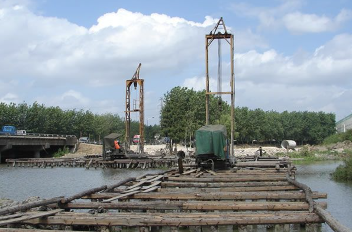
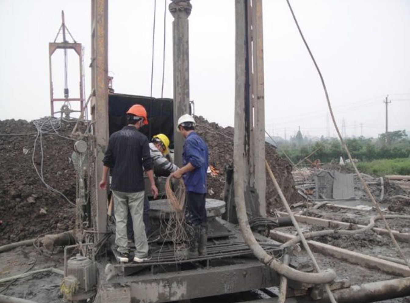
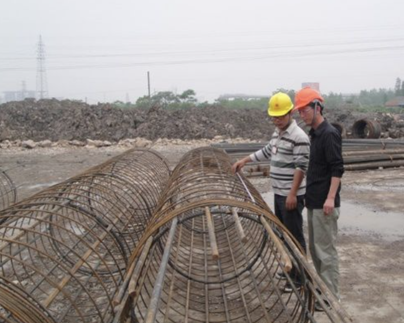
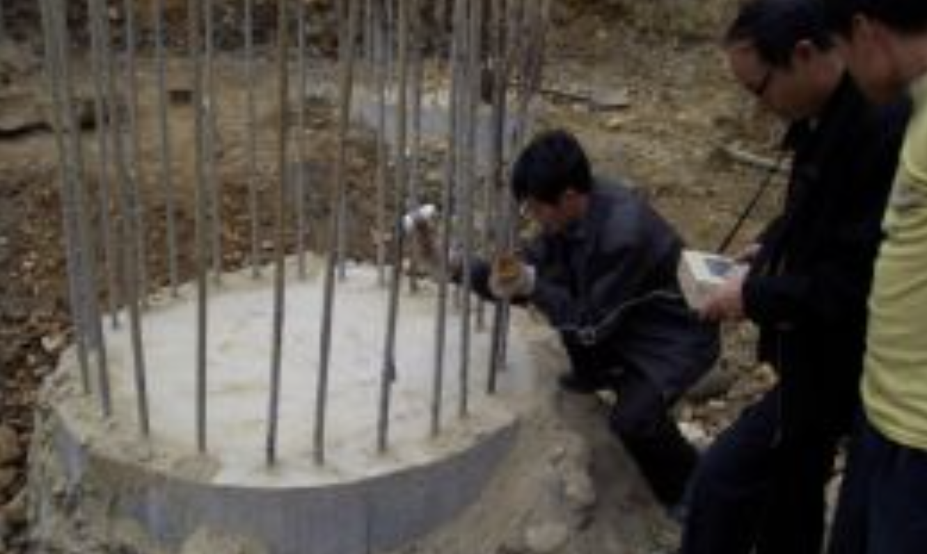
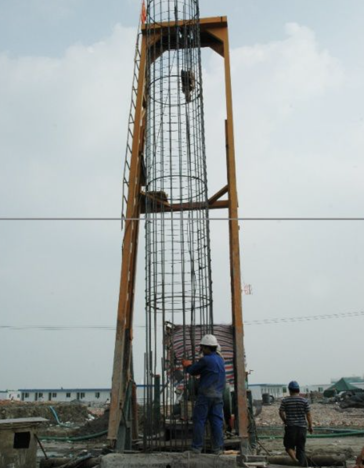
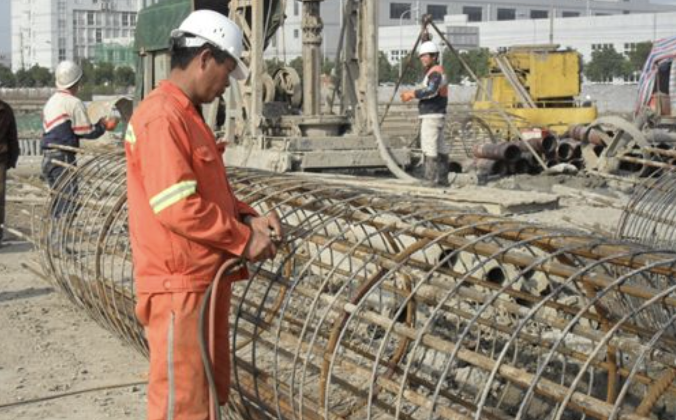
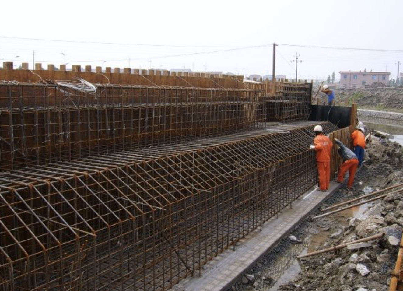
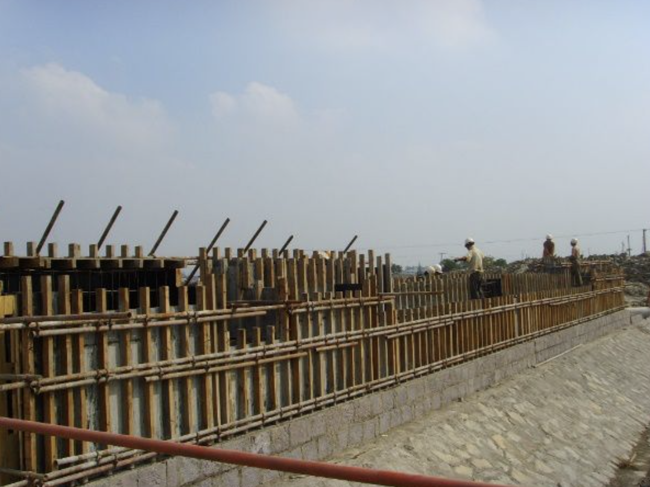
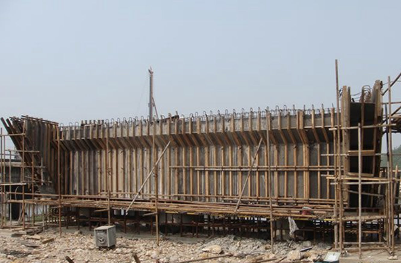
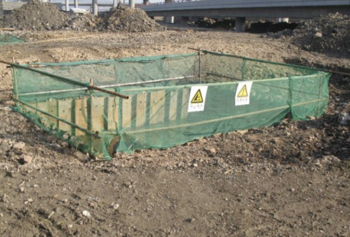
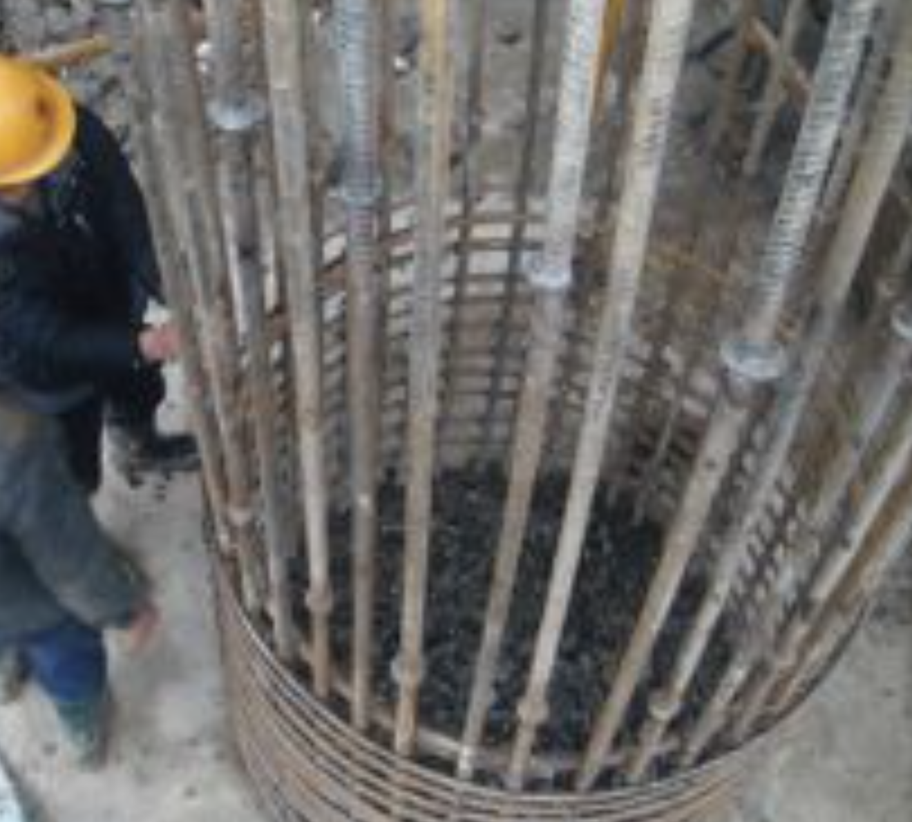
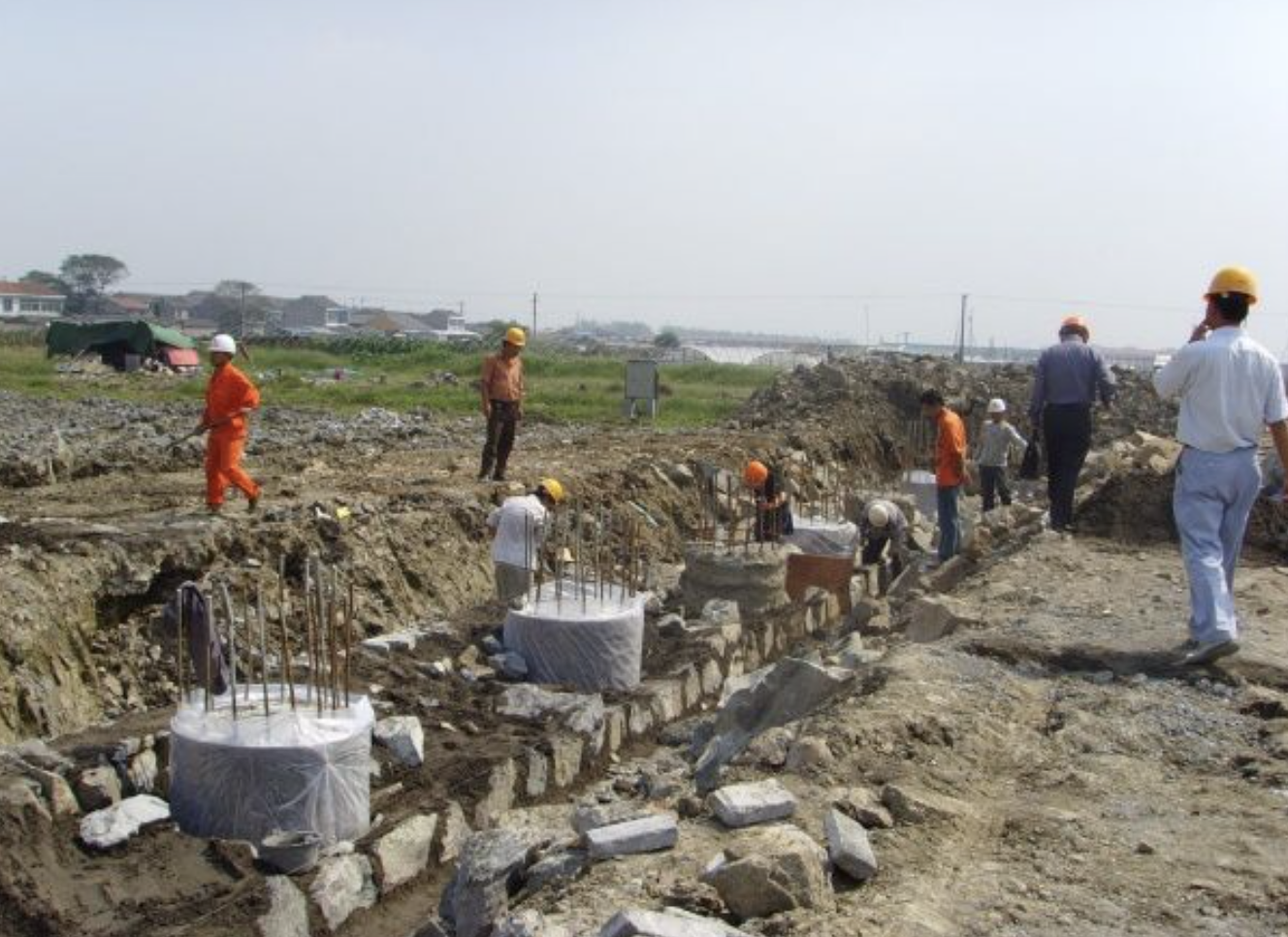
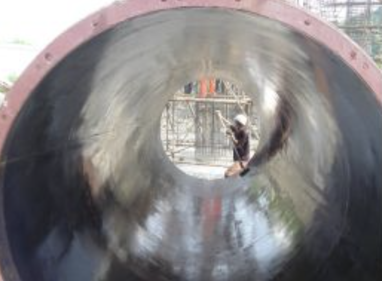
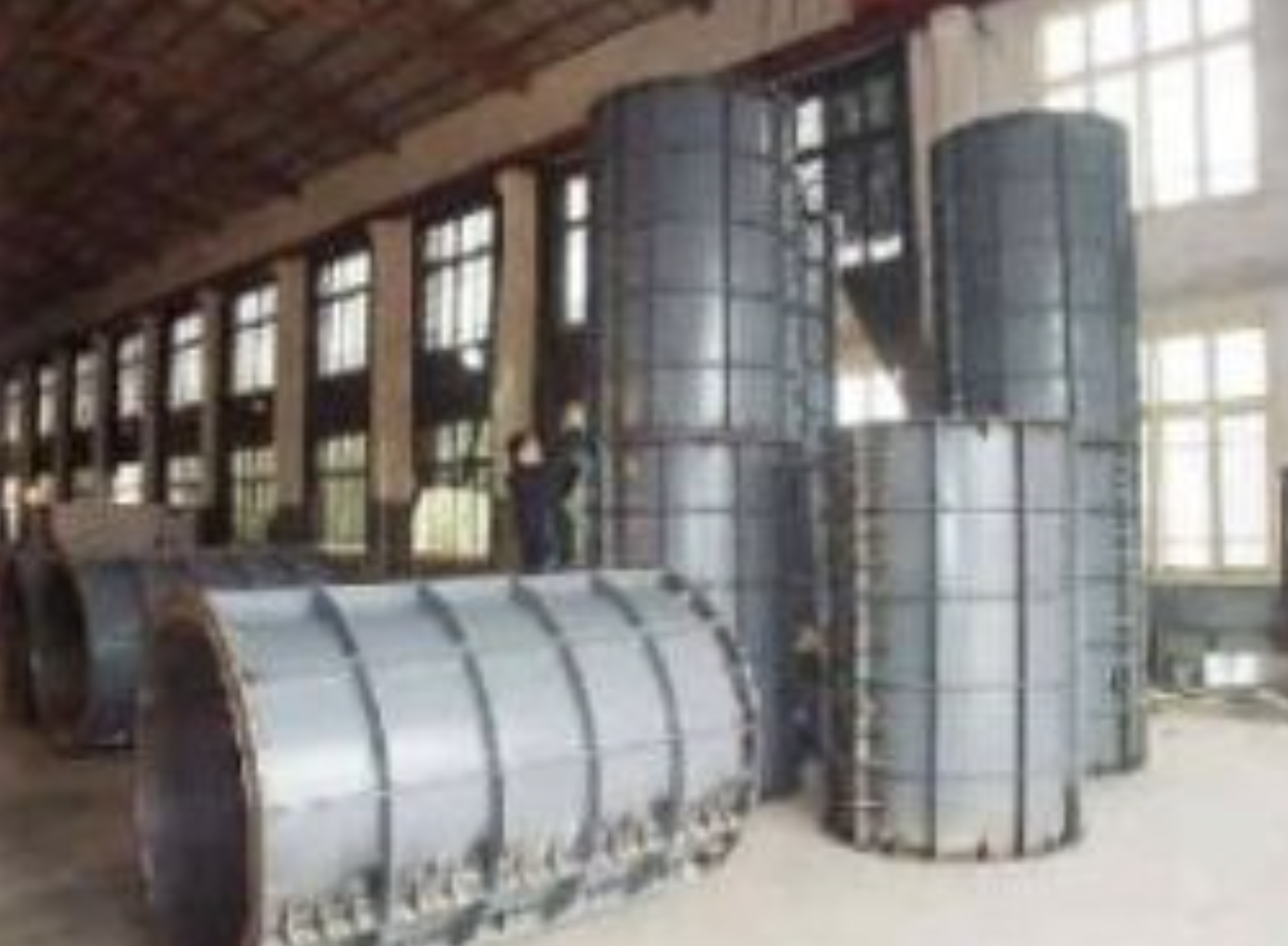
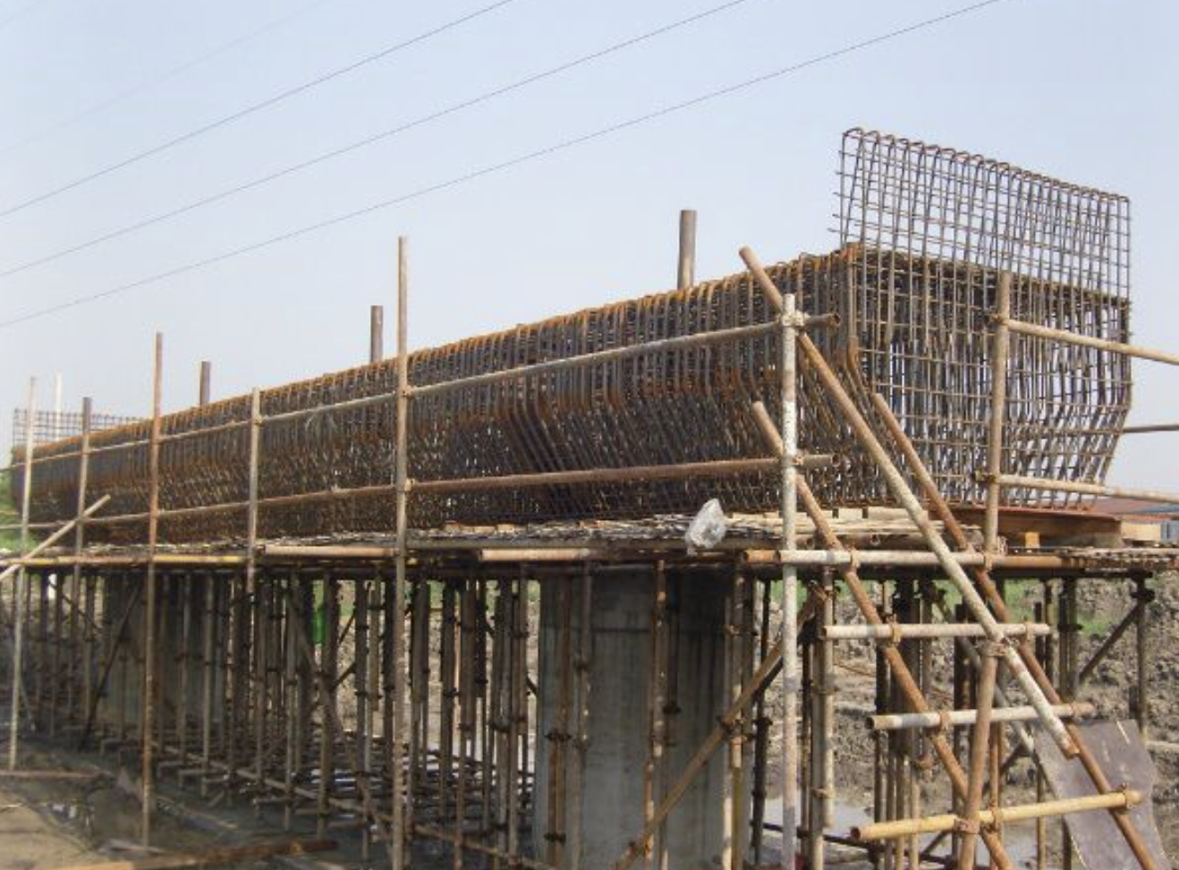
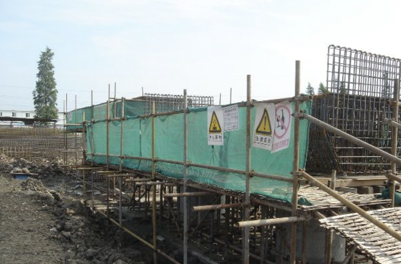
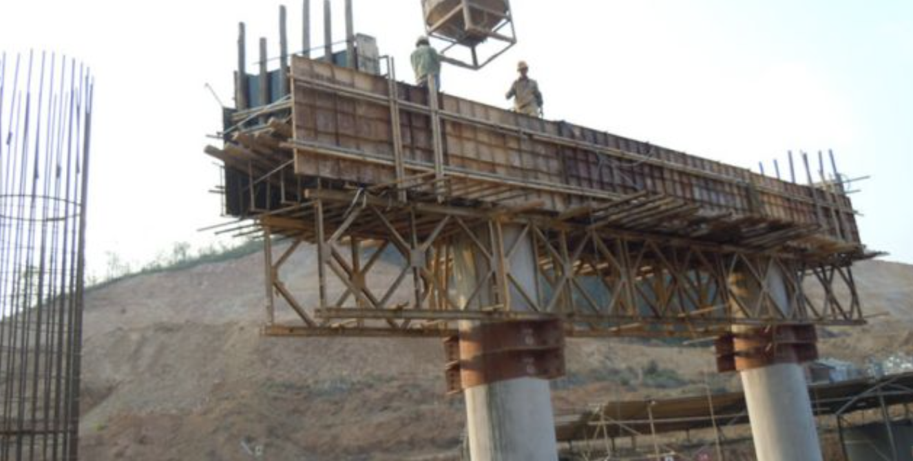
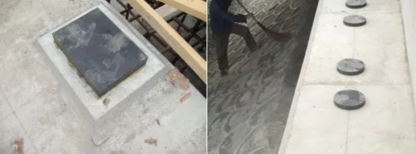
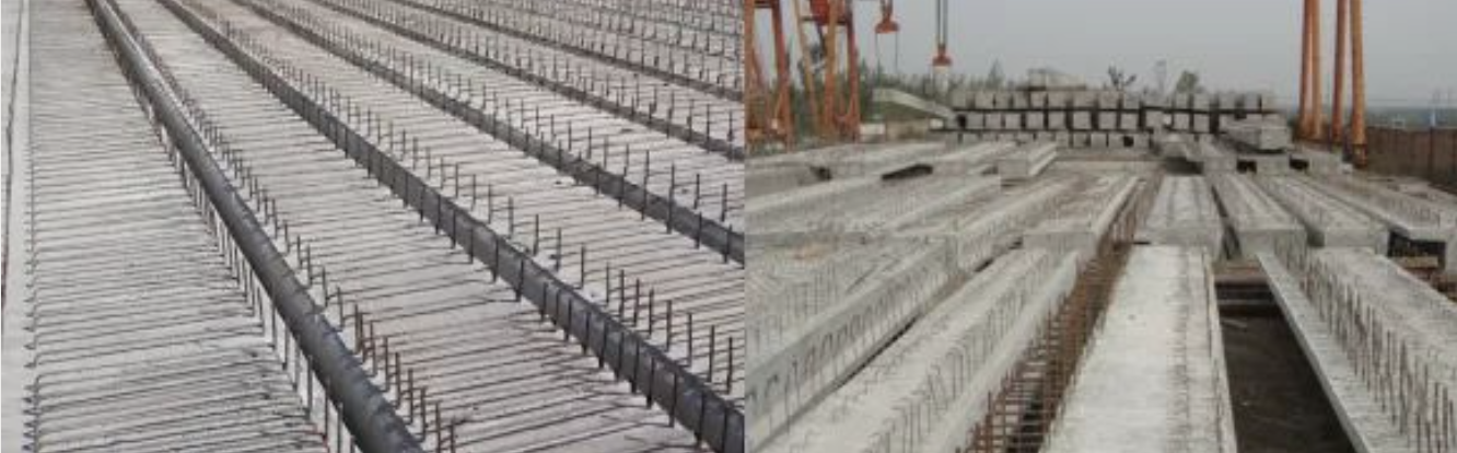
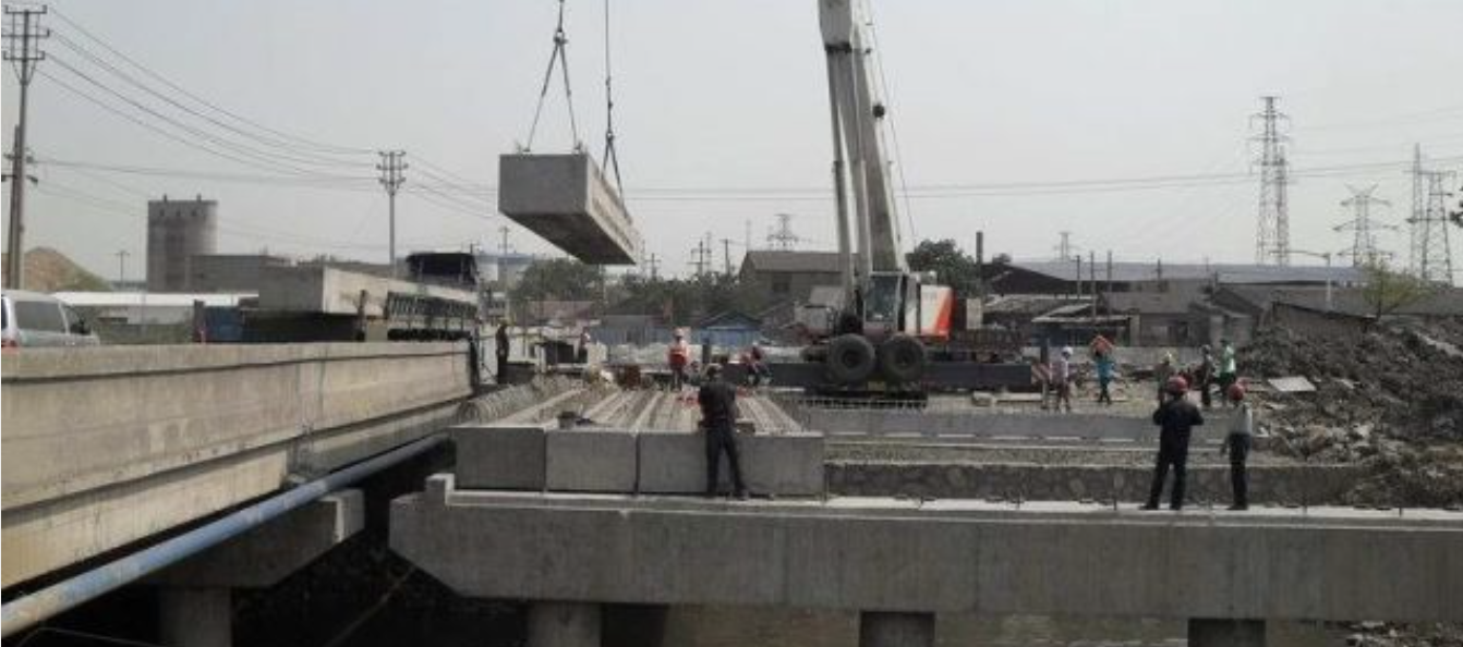