
Project Overview of Bored Piles
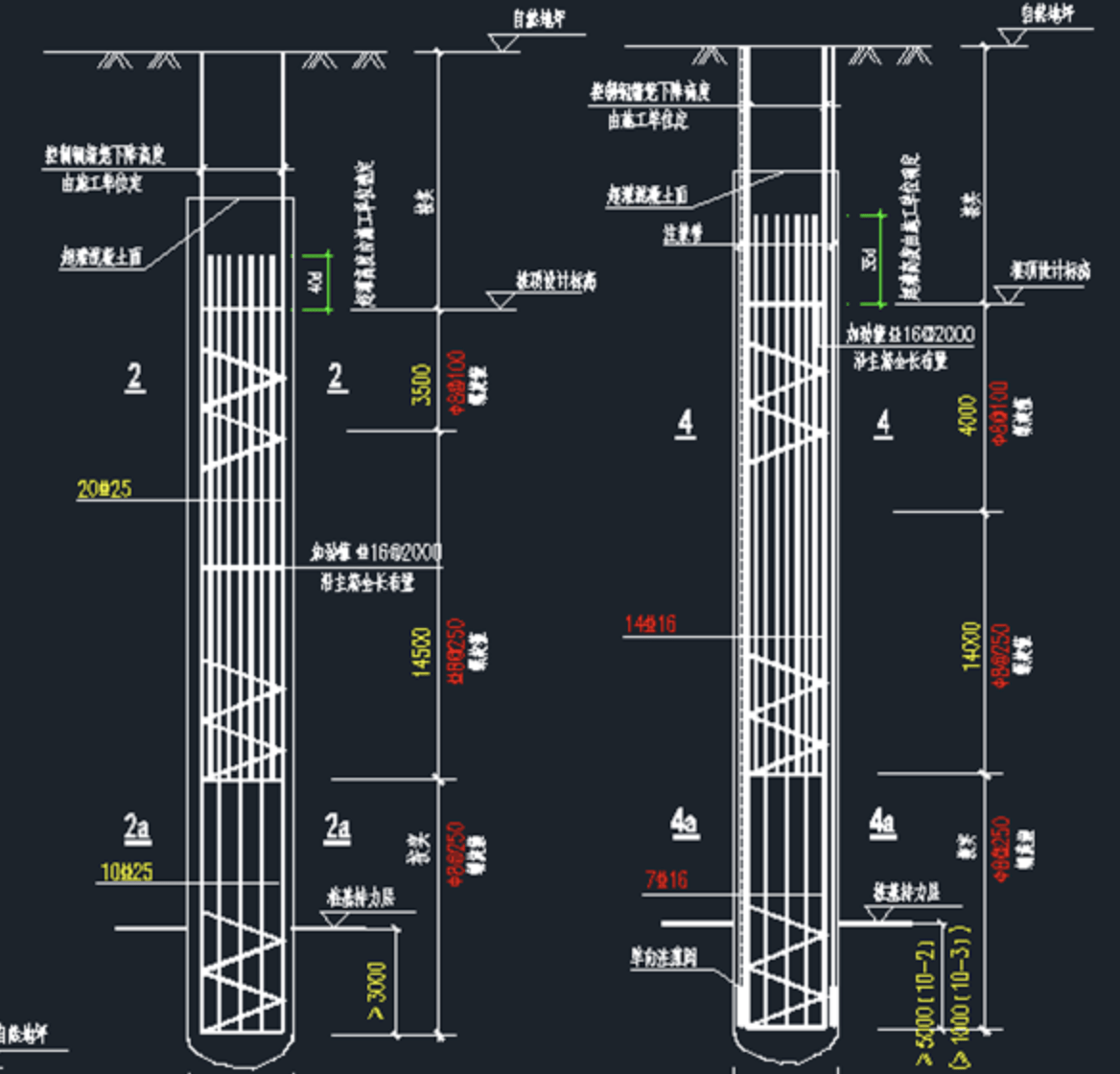
This project features a ±0.000 absolute elevation of 5.050, with natural ground elevation at -0.550. The excavation depth reaches 15.2 meters, extending to 17.05 meters in specific areas and 19.85 meters in elevator pits. The foundation piles consist of Φ700 and Φ800 bored cast-in-place piles, with the Φ800 piles requiring post-grouting.
Key specifications:
-
Φ700 piles penetrate 3 meters into the 10-2 strongly weathered breccia tuff bearing stratum
-
Φ800 piles either penetrate 5 meters into 10-2 stratum or 1 meter into 10-3 moderately weathered breccia tuff
-
Excavation dimensions: North side 158m, West side 211.7m, South side 178m, East side 271m
-
Total excavation area: 36,516m² with approximately 570,000m³ of earthwork
-
Base soil composition: silty clay with淤泥 quality
-
Foundation pit design safety rating: Grade I according to technical specifications
Quality Control for Bored Cast-in-Place Piles
Quality Requirements
-
Project target: Luban Award (China’s highest construction quality honor)
-
Pile quality standard: 98% must meet Class I pile standards
-
Zero tolerance for Class III piles
Construction Process Flow
1. Construction Preparation
-
Plan site access roads, considering all construction factors
-
Install water supply, power, and drainage systems
-
Configure mud pits, sedimentation tanks, and mud channels per layout
-
Install and test equipment (Drill rig model: PS-10)
-
Verify material certifications and conduct pre-construction testing
2. Survey Layout
-
Verify and protect all control points and benchmarks
-
Mark pile positions with steel nails and red paint triangles
-
Measurement protocols:
-
Protect all survey markers with visible identification
-
Verify positions through triple-check system (technician → supervisor → client)
-
Maintain complete measurement records
-
Tolerance: <±5mm control error, <20mm pile position deviation
-
3. Steel Casing Installation
-
Specifications:
-
Length ≥1.2m, thickness=5mm
-
Φ700 piles: 800mm inner diameter casing
-
Φ800 piles: 900mm inner diameter casing
-
-
Installation requirements:
-
Top elevation above the groundwater level
-
Verticality tolerance <1/200
-
Ovality ≤2cm
-
Full penetration welding for watertightness
-
Bottom embedded ≥0.2m into natural soil
-
Center deviation ≤20mm
-
4. Drilling Rig Positioning
-
Level the rig base using precision instruments
-
Center deviation <20mm
-
Four-direction leveling error <1/200
5. Mud Process
-
Natural mud formation based on geological conditions
-
Continuous monitoring and waste mud removal
6. Drilling Process
-
Optimize parameters (speed/pressure) for different strata
-
Implement skip drilling when pile spacing <4D (D = pile diameter)
-
Alternative: 36-hour interval between adjacent piles
-
Depth control:
-
Minimum: design depth
-
Maximum over-drilling: 30cm
-
-
Verticality tolerance: <1/100
-
Position deviation: <50mm
7. Hole Cleaning
Two-stage process:
-
Primary cleaning: Using drilling tools (≥30 minutes)
-
Secondary cleaning: Through the tremie pipe after rebar cage installation
-
Final sediment thickness: ≤100mm
-
Time between cleaning and concreting: ≤30 minutes
8. Rebar Cage Construction
Fabrication standards:
-
Segmented fabrication (9m standard lengths)
-
50% staggered lap joints
-
Protection layer: 60/50mm (±20/-10mm tolerance)
-
Spiral ties: 50% spot welded in checkerboard pattern
-
Welding requirements:
-
Main bars: 10D single-side full weld
-
E43 rods for Grade I steel, E50 for Grades II/III
-
-
Installation controls:
-
Maximum 2-layer stacking
-
Verticality tolerance <1%
-
Center deviation ≤10mm
-
Elevation control using measuring rods
-
9. Underwater Concrete Placement
Material specifications:
-
Compressive piles: C40 concrete (underwater grade +2 levels)
-
Tension piles: C30 concrete (underwater grade +1 level)
-
Slump: 180-220mm
-
Initial set: 6-8 hours
Placement protocol:
-
Tremie pipe bottom clearance: 0.5m
-
Initial charge volume: ≥1.5m embedment
-
Continuous placement duration: ≤8 hours
-
Embedment depth: 2-6m during placement
-
Maximum lift per cycle: ≤10m
-
Overpour height: ≥2m
-
Bulking factor: 1.0-1.3
Quality controls:
-
Sampling: 150mm cubes @ 50m³ or 1 set/pile
-
Curing: 20±2°C @ 95% RH for 28 days
-
Night work restrictions: Use high-density mud for temporary hole sealing
10. Quality Assurance Measures
Critical control points:
-
Survey accuracy (position/verticality)
-
Mud properties (density/viscosity/sand content)
-
Hole quality (verticality/diameter/depth/sediment)
-
Rebar cage (connections/specs/spacing/accessories)
-
Concrete (grade/mix/placement rate/slump)
Testing protocol:
-
Steel: 60T batches (tensile/bend tests)
-
Concrete: 50m³ batches (compression tests)
Post-Grouting Construction Methodology
1. Grout Pipe Installation
-
Material: Φ25×3.2mm steel pipes
-
Configuration: 2 pipes/pile (symmetrical)
-
Valve design:
-
16×7mm one-way outlets
-
Rubber wrapping for sealing
-
20-50cm embedment below the pile tip
-
Installation requirements:
-
Secure binding to main bars @1.5-2.0m intervals
-
Water pressure test after installation
-
Top protection with threaded caps
2. Water Fracturing Test
-
Timing: 7-8 hours after concreting
-
Parameters:
-
Volume: 0.2-0.6m³
-
Duration: 3-5 minutes
-
Pressure: 0.2-0.5MPa
-
3. Grouting Process
Equipment:
-
Grout pump: ≥6MPa capacity
-
Hoses: 10MPa rated, Φ25mm ID
Materials:
-
Cement: Fresh P.O 42.5
-
Mix ratio: 0.55-0.6 W/C
-
Filtration: ≤3mm mesh
Operation:
-
Initial pressure: Test pressure ×1
-
Final pressure: Test pressure ×2-3
-
Flow rate: 30-40L/40L/min
-
Balanced injection through both pipes
Termination criteria (whichever comes first):
-
Design volume achieved OR
-
Pressure >2MPa for 3 minutes @ 80% volume
4. Quality Assurance
-
Material certification and testing
-
Valve fabrication inspection
-
Pipe positioning verification
-
Pressure/flow monitoring
-
Complete documentation
-
Load testing after 20 days
Common Defect Prevention Measures
1. Hole Deviation
Causes: Unstable rig setup, bent drill pipe, uneven ground
Solutions:
-
Proper site leveling
-
Regular tool inspection
-
Guide stabilizers
-
Correction methods: Reaming or clay backfill
2. Hole Collapse
Prevention:
-
Skip drilling pattern
-
Optimized mud properties
-
Casing depth adjustment
-
Continuous operation (<3hr standby)
3. Diameter Variation
Control methods:
-
Tool maintenance
-
Parameter adjustment
-
Reaming operations
-
Mud pressure management
4. Pipe Blockage
Avoidance:
-
Proper tremie seals
-
Slump control
-
Equipment maintenance
-
Gradation compliance
5. Rebar Cage Floatation
Countermeasures:
-
Secure positioning
-
Placement rate control
-
Embedment monitoring
-
Emergency stop procedure
6. Defective Piles
Prevention:
-
Thorough hole cleaning
-
Continuous placement
-
Mix design compliance
-
Proper lifting technique
7. Cage Settlement
Remedies:
-
Shallow settlement: Extension
-
Deep settlement: Supplemental piles
Pile Testing Protocol
-
Test method: Static load testing
-
Test quantity: ≥1% of total piles
-
Timing: After 20-day curing (post-grouting)
-
Criteria: Per JGJ94-2008 specifications
