
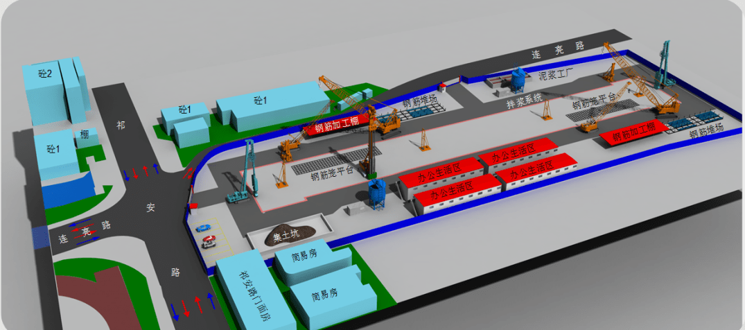
Venue Layout
The construction site mainly includes three parts: the underground diaphragm wall forming area; the mud system area; and the steel cage processing area. The three areas are connected by access roads, and the mud system pipelines must be routed to the underground diaphragm wall area.
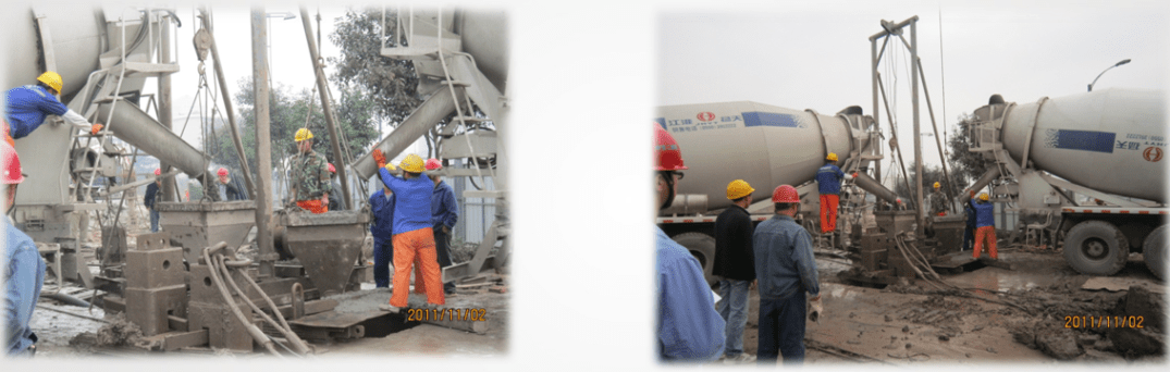
According to the geological and structural characteristics, the construction of the ground connecting wall of this project adopts the “grabbing and milling combination” trough forming process, that is, the shallow silt and clay composite stratum is formed by a hydraulic grab to form the trough, and after entering the rock layer, a milling troughing machine is used to form the trough. construction.
To minimize the area occupied by the mud system, a mud system is adopted that combines a mud silo with an existing mud pool. The mixing, screening, and circulation of the mud are mainly completed in the mud pool, and the storage is mainly done in the mud silo. The mud silos are divided into two systems that are not connected. Silo group A stores mud in troughs, and silo group B stores mud specifically for bottom cleaning and mud changing.
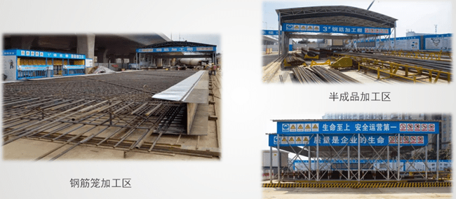
Rebar Processing Area
In principle, the ground wall steel cage processing area is set up near the ground wall trough area to facilitate the transportation and installation of the steel cage. Based on compacting the original ground at the processing site, gravel is laid and a concrete surface layer is poured. The size of the processing site is set according to the size of the longest section of the steel cage. The steel cage is processed as a whole in unit trough sections. The site can process the steel cages of two trough sections at the same time. Set up a raw material storage area, a semi-finished product processing area, and a steel cage stacking area near the steel bar processing site.
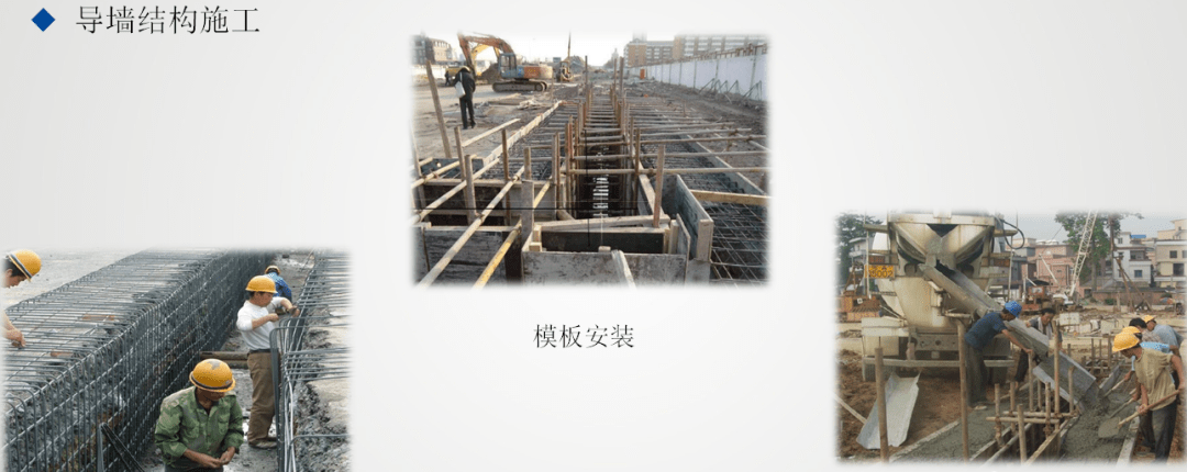
Construction Technology
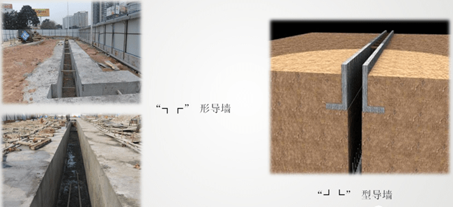
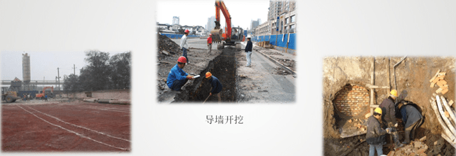
Guide wall production
The guide wall is the key to ensuring the accurate position of the underground diaphragm wall and the quality of the groove. During construction, the guide wall often bears static and dynamic loads such as steel cages, conduits for pouring concrete, and mechanical equipment. Therefore, it must be carefully designed and constructed. Only then can the formal construction of the underground diaphragm wall be carried out.
Effect
◆ Guide the groove-forming machine;
◆ Store mud and prevent slot collapse;
◆ As the benchmark for horizontal and vertical measurements during construction;
The guide wall generally adopts a cast-in-place reinforced concrete structure and also has a steel or prefabricated reinforced concrete assembly structure. Design and construction based on different soil characteristics.
◆ Measurement and positioning, pipeline planning, and inspection
Measure and stake out the outer edge of the main structure according to the coordinates of the drawing. The center line and sideline positions of the guide wall are reflected through the outer edge line. The center line position of the guide wall coincides with the center line position of the ground wall.
Measure the ground elevation and measure the depth according to the drawing requirements to carry out guide wall excavation. Since the underground diaphragm wall will undergo inward displacement and deformation under the action of the external soil pressure during foundation pit excavation, to ensure that the clearance of the later foundation pit structure meets the requirements, the center line of the guide wall will generally be exposed outward, and the amount of external exposure will be based on the design requirements and The structural depth is comprehensively determined.
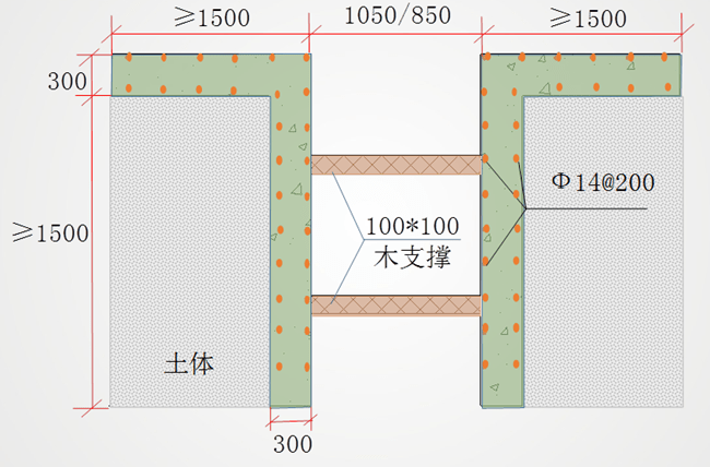
◆ The guide wall is set 1.5m higher than the groundwater level, the wall toe enters the original soil layer by more than 300mm, and the bottom elevation of the guide wall is at least 20cm lower than the top elevation of the ground connection wall. If the original soil in the guide wall construction area is damaged the soil is loose, and the wall toe cannot enter the solid undisturbed soil layer, the soil must be reinforced before the guide wall is constructed.
◆ According to the pipeline location on the pipeline distribution map, clear the road surface above the area where the pipeline needs to be cut. And detect the specific location of the pipeline. After the pipeline is broken, the waste gas pipeline section is blocked and the area is backfilled with cement and soil.
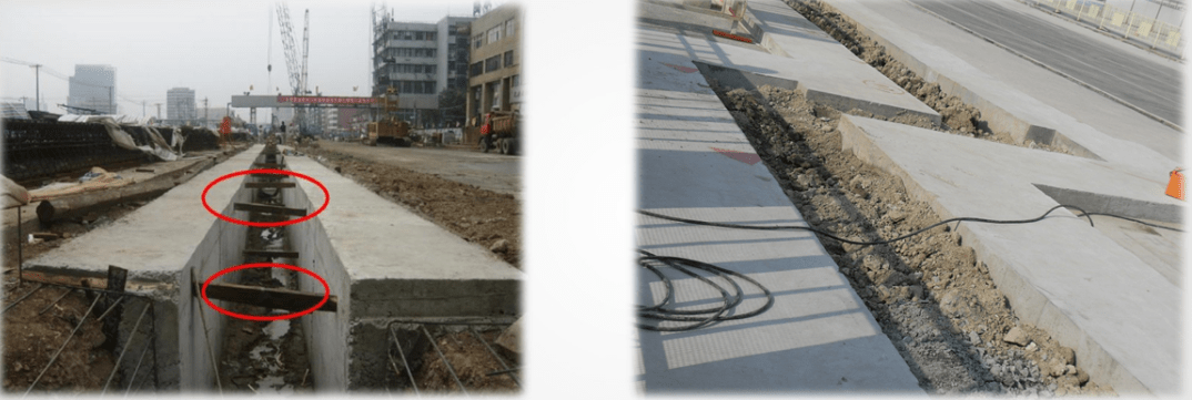
Remove the formwork after the concrete strength reaches 5MPa. Immediately after removing the formwork, re-check the central axis and clearance size of the guide wall and the pouring quality of the side wall concrete. If it is found that the side wall concrete has invaded the clearance or a cavity appears in the wall, it should be repaired or blocked in time. Immediately after the formwork is removed, wooden supports are erected, one at the top and one at the bottom, arranged in a plum blossom shape, with a spacing of 1.0~1.5m. After passing the inspection, earthwork backfilling will be carried out immediately to prevent the displacement of the guide wall. Before the concrete of the guide wall reaches the design strength, any heavy machinery and transportation equipment are prohibited from passing next to it. At the same time, use red paint to mark the dividing lines on the top wing of the guide wall and mark the amplitude number. The construction joints of the guide wall are connected with the underground Wall joints and are staggered.
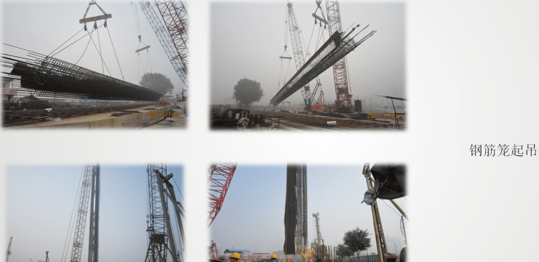
Steel cage production
According to the steel cage design drawings, draw the processing drawings of the steel cage before production. According to the layout requirements of the conduit, reserve the position of the pouring conduit in advance. Two grouting pipes are welded to the appropriate positions of the steel cage according to the design. The steel bar connector is set on the steel cage according to the layout plan of the main structure. The foundation pit monitoring component is pre-embedded on the steel cage according to design requirements. All embedded parts must be installed accurately.
The commonly used flexible joint ground wall steel cage processing process is generally: erection of steel processing platform – fixation of bottom horizontal bars and joints – fixation of bottom main bars and horizontal bars – longitudinal trusses – transverse trusses – top main bars – top layer Distributed reinforcement – hanging point reinforcement, joint reinforcement.
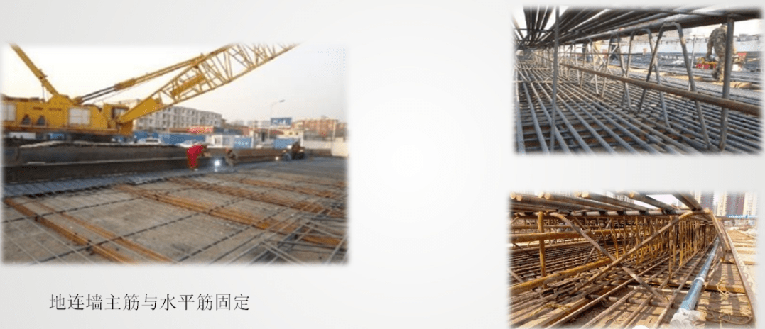
The steel cage processing platform should have strong rigidity and stability to prevent the steel cage from deforming due to its weight during platform processing. In actual operation, profiles such as channel steel and I-beam can be welded with steel bars to form a platform. The length of the platform is determined according to the length of the steel cage.
To prevent the steel cage from irreversible deformation during the lifting process, various shapes of steel cages are equipped with longitudinal and transverse truss bars. During construction, the truss bars are welded in strict accordance with the design and specification requirements to ensure the stiffness of the steel cage itself.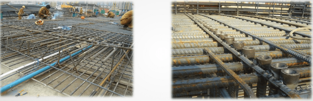
◆ Pre-embedded equipment required for monitoring, such as inclinometer tubes, acoustic tubes, earth pressure gauges, and other equipment, should be properly laid out when making the ground-connected wall steel cage to avoid conflict with subsequent concrete conduits. All exposed cables must be cased fixed and wrapped tightly to prevent the steel cage from shifting during hoisting and concrete pouring and prevent the monitoring work from being filled with grout in the pipe.
◆The steel bar connector of the underground diaphragm wall is a connector that is pre-embedded on the steel cage of the underground diaphragm wall according to the elevation requirements of the future underground structure floor during the construction of the diaphragm wall steel for the overall connection of the underground diaphragm wall and the floor. After the foundation pit is excavated, the pre-buried connector
It is common for connectors to be corroded, screw threads damaged, and the azimuth angle deviation is large, resulting in connectors and structural main bars being unable to connect, not screwing in place, and connection difficulties, etc., causing some connectors to be unable to connect to the steel bars of the main structure, affecting structural walls. To ensure the integrity of the slab, it is often necessary to install additional reinforcements and then connect them.
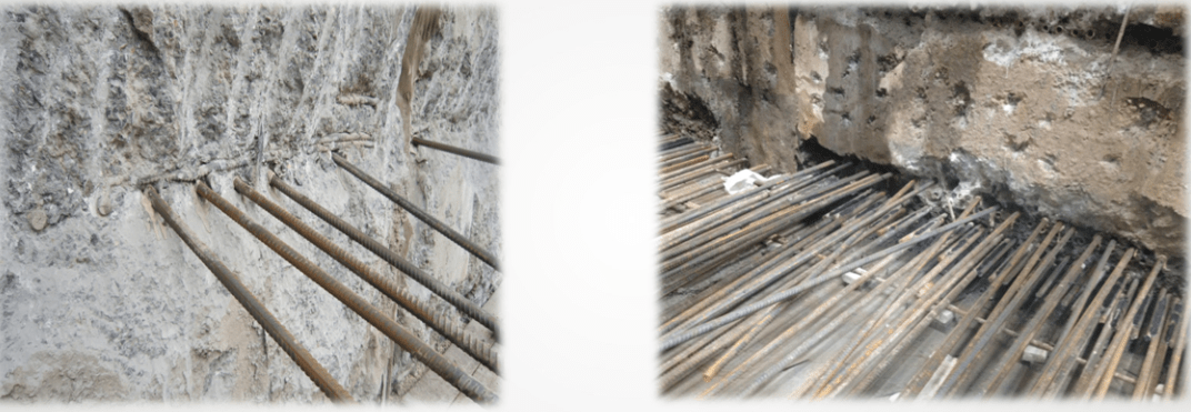
◆Cause analysis
① The flatness of the steel cage itself is not enough, the connector and the distribution bars are in point contact, the positioning is difficult to control, and the welding joint is prone to deformation.
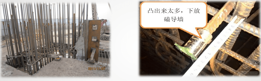
② The screw threads of the connector were damaged when the underground diaphragm wall was chiseled after the foundation pit was excavated.
③ During the process of hoisting the steel cage into the slot, it rubbed against the guide wall, causing the connector cover to fall off.
④ The reserved design of the connector does not consider the settlement of the steel cage.
By analyzing the quality problems that are prone to occur in connector construction, we consider improving the construction quality of two-point connectors to overcome connector positioning deviations, screw thread damage, corrosion, and other shortcomings.
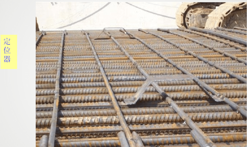
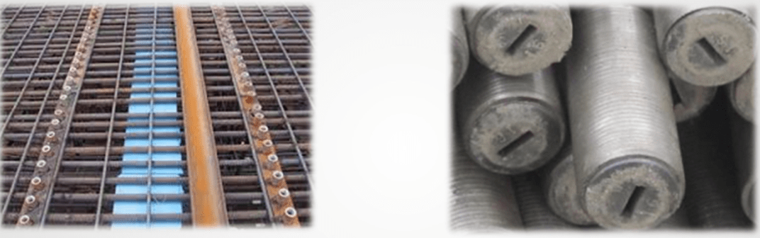
◆ To ensure that the connector is accurately positioned and meets construction requirements, it is necessary to position and control the connector before welding and fixing it on the steel cage, and then weld and fix it. Therefore, the solution is to add a “locating card” device to the connector. Angle steel can be used. Horizontal spot welding of angle steel at the elevation of the steel cage connector replaces the traditional wire-pulling method. The height control of the connector is based on the edge of the angle steel. The connector rests on a flat surface of the angle steel and is welded and fixed after positioning.
◆ The strip-shaped cover plate is designed to resemble an “L” shape. After the separate cover of the connector is screwed into position, insert the strip cover plate along the connecting direction of the connector. Generally, aluminum color steel plates are used to make strip-shaped replacements, which are capped along the direction of the connector connection and tightened with thin iron wires. When digging the protective layer of the underground diaphragm wall, theoretically the protective layer of the connector section will also fall off in strips.
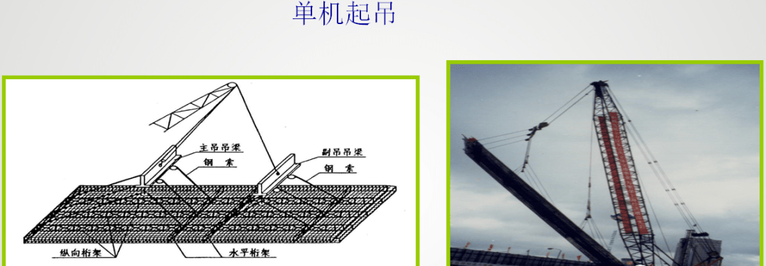
Steel cage lifting
The lifting of the steel cage is usually carried out by a crawler crane because after the steel cage is lifted, the crane needs to transport the vertically lifted steel cage to the opening for lowering.
The lifting and placement of the steel cage should be based on its weight and length, and a matching crane should be selected. Generally, single-machine lifting or double-machine lifting is used, and it is commanded by a dedicated person. When entering the tank, the cage should be lowered slowly and smoothly, and should not be forced down quickly. After entering the tank, the cage top elevation should be accurately controlled based on the measured guide wall elevation.

Points to note when hoisting steel cages
⑴ Before hoisting the steel cage, the construction plan must be evaluated by experts before hoisting. The steel cage should be subjected to “three quality inspections”, the “Concealed Engineering Acceptance Form” should be filled out and the supervisor should apply for an acceptance visa. Otherwise, the hoisting operation cannot be carried out.
⑵ Before hoisting the steel cage, the direction of the excavation surface should be clear, because the reinforcement between the excavation surface and the soil surface is often asymmetrical. If you make a mistake, the stress conditions will be opposite.
⑶ If a crawler crane is used to lift the steel cage over a long distance, the steel cage must be suspended vertically.
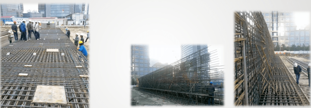
⑷ When hoisting the corner steel cage, a “herringbone” truss should be set up, and some special diagonal tie rods should be added to strengthen its stiffness to prevent the steel cage from deforming. When the steel cage is lowered into the groove, it should be gradually dismantled.
Steel cage underneath
After the steel cage is made, check the number and location of all embedded parts, steel connectors, and monitoring equipment before lifting. Check whether the installation of the monitoring equipment is accurate and meets the quality standards before lifting into the slot.
Before hoisting the steel cage, the elevations of the four fulcrums on the guide wall should be reviewed again, and the length of the hanging bars should be accurately calculated to ensure the accuracy of the position of the steel cage. After the steel cage is lowered into place, since the position of the lifting point is not completely consistent with the measuring point, the hanging bars will be elongated, etc., which will affect the height of the steel cage. The height of the top of the steel cage should be measured immediately with a level gauge, and adjustments should be made according to the actual situation. Adjust the cage roof elevation to the design elevation.
When setting up the steel cage, align it with the central axis of the trough section, lift it straight and steady, and sink slowly to avoid collision with the hole wall.
When the lower steel cage is lowered to the opening, reinforced channel steel is used to stabilize the reinforced top of the steel cage and erect it on the guide wall. Then lift the steel cage of the upper section. After it is vertical, make the main bars of the upper and lower sections pair up one by one and connect them with U-shaped buckles.
When the steel cage approaches the predetermined elevation, check the plane position of the cage and make adjustments if it exceeds the standard. When the steel cage is lowered to the predetermined elevation, use channel steel to stand the steel cage on the guide wall, and use a level to calibrate the top elevation of the channel steel to ensure it is on the same horizontal plane.
Steel cage manufacturing requirements
1. The steel cage processing site and production platform should be flat. The steel cages made in sections should be assembled when they are made in the same tire, using welding or mechanical connection. The overlap length of the main bar joints should meet the design requirements, and the overlap positions should be staggered by 50%. Third-grade steel and second-grade steel above Φ25 should be mechanically connected.
2. The lifting truss of the steel cage should be determined based on the calculation results of the stiffness and overall stability of the steel cage during the lifting process.
3. The intersection points of the main bars of the steel cage should be 50% spot-welded and evenly distributed, and the main bars, trusses, and lifting points should be 100% spot-welded.
4. The steel cage should be equipped with protective layer pads, with a longitudinal spacing of 3m to 5m and 2 to 3 transverse pads. The positioning pads should be made of 4mm to 6mm thick steel plates in a “shape and welded to the main bars.
Hoisting requirements for steel cages
1. The selection of the crane should meet the requirements of hoisting height and lifting capacity. The main crane and auxiliary crane should be determined based on calculations.
2. The layout of the lifting points of the steel cage should be determined based on the lifting technology and calculations, and the safety check such as the stiffness of the overall lifting of the steel cage should be carried out. The spreaders, lifting point reinforcement steel bars, and hanging bars should be configured according to the calculation results. The length of the hanging bars should be determined based on the measured guide wall elevation.
3. Before lifting the steel cage, check that there are no obstacles within the 600mm radius of the crane’s rotation, and conduct a trial lifting.
4. When hoisting the steel cage, it should be aligned with the center line of the trough section and sink slowly, and it should not be forced into the trough.
5. The soil-facing surface and pit-facing surface of the steel cage should be placed in the correct direction, and reverse placement is strictly prohibited.
6. The steel cage should be hoisted in time after the foundation is cleared.
7. Before lifting the special-shaped trough section steel cage, the corners should be strengthened and gradually cut off as the trough is entered.
Quality control of steel cage production
1. The flatness of the steel bar production platform should be controlled within 20mm.
2. The installation error of the steel cage should be less than 20mm.
Mud preparation
The mud exerts pressure on the trench wall to protect the shape of the dug-deep trench, and the mud is displaced when the concrete is poured. Slurry materials usually consist of bentonite, water, chemical treatments, and some inert substances.
Effect
◆Form an impermeable mud skin to prevent groundwater seepage and the tank wall from peeling off, and keep the tank wall stable.
◆Cooling and lubricating equipment
◆Suspend soil and carry soil out of the ground
According to the geological conditions of the site, bentonite mud is generally used as mud, and its material composition includes bentonite, CMC (cellulose), Na2CO3 (soda ash), and water.
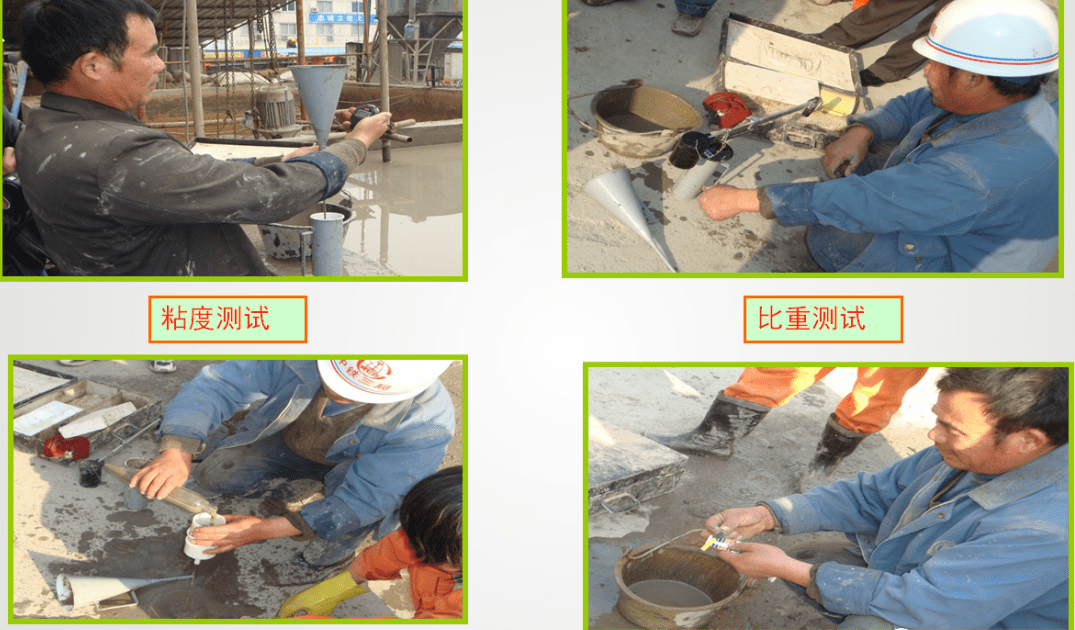
Quality Control
During the construction of underground diaphragm walls, the properties of mud will deteriorate due to various factors. The main reasons are: the consumption of mud due to the formation of mud skin, the dilution of mud by groundwater or rainwater, the mixing of fine clay particles into the mud, and the Calcium ions mixed into the mud, and cations in the soil or groundwater are mixed into the mud.
◆ 2 to 3 sections of ground connection wall construction are used as test sections. Through the test section, the specific gravity, viscosity and other performance indicators of the troughing and clearing mud can be understood, and the mud mix ratio can be adjusted and optimized in the subsequent ground connection wall construction.
◆ During mud production, two quality indicators are tested for each shift. The fresh mud must be stored for 12 hours to fully expand before use and must be continuously stirred by a mud pump in the mud pool.
◆ During the process of forming the trough, the mud surface must be 0.5m higher than the groundwater level. The mud in the trough must be tested regularly. It is also necessary to pay full attention to the impact of surrounding environmental conditions on the mud quality, such as changes in the groundwater level, the soil quality of the discharged muck, and the original quality of the trough. There are differences in the geological conditions of the survey, which prevents mud from overflowing to the outside of the guide wall and prevents rainwater and groundwater from flowing into the trench.
◆ After the tank is formed, the mud remains in the tank for a long time, and the mud in the tank will easily reduce its quality. The soil residue suspended in the mud will precipitate, thus reducing the specific gravity of the mud, which will make the formed mud skin weak and have poor anti-seepage properties. Therefore, during the mud resting time, some freshly mixed mud should be appropriately added to the tank and the quality should be checked regularly.
◆ The used mud passes through the desander to remove soil particles and gravel, and then the clean mud is returned to the tank. After the groove is formed, the groove milling machine is placed at the bottom of the groove, the used mud is pumped out, and recycled through the desander, while fresh mud is supplied to the upper part of the groove. This process continues until the slurry meets the specified standards for lifting the steel cage and pouring concrete.
Trench construction
The selection of floor-to-ground wall trough forming equipment is a key link in the hole-making construction process. An overall overview analysis must be carried out based on the geology, construction period, hole depth, underwater concrete pouring, cost, and other requirements of the actual project, and a scientific and reasonable Compare and select, initially determine the basic form of troughing equipment, especially conduct an in-depth and detailed analysis of the engineering geological conditions, extract key geological data of each section, predict various possible construction difficulties, formulate countermeasures, and use this as a basis The important basis is to determine the specific form, function, structure and other parameters of the troughing equipment.
According to the geological and structural characteristics, the ground connecting wall of this project adopts the “grabbing and milling combination” trough forming process, that is, the shallow silt and clay composite stratum is formed with a hydraulic grab to form the trough, and after entering the rock layer, a milling machine is used to form the trough.
Due to the characteristics of the diaphragm wall joints in this project, the trenching construction adopts the troughing method. According to the length of the trough section and the opening width of the troughing machine, the first opening and closing widths are determined to ensure the balance of the adjacent conditions on both sides when the troughing machine cuts the soil. properties to ensure that the tank walls are vertical.
■ According to the construction sequence, it can be divided into three types: first opening width, continuous width, and closed width.
◆ First opening
Hydraulic grab grooving → double-wheel milling and excavation → lowering both ends to install CWS joints → slurry replacement and ballast removal → Steel cage hoisting → concrete pouring → First opening completed.
◆ Continuous width
Hydraulic grab grooving → double-wheel milling and excavation → pulling out the CWS joint on one side of the constructed width → Lowering and installing the CWS on the other side → replacing the slurry and removing ballast → hoisting the steel cage → concrete pouring → the completion of this width.
◆ Closing width
Hydraulic grab grooving → double-wheel milling and excavation → pulling out the CWS joints at both ends → replacing the slurry and removing ballast → Hoisting the steel cage → concrete pouring → this section is completed.
Hydraulic grab
During the trenching construction, a hydraulic grab is first used to excavate the trench section. The impact force and closing force of the hydraulic grab are enough to grab the layers above the strongly weathered rock. During the trenching process, the verticality and plane position of the grab are strictly controlled. Especially the grooving stage. Observe the monitoring system. If the deviation in any direction of the X or Y axis exceeds the allowable value, correct the deviation immediately. The grab bucket is inserted into the slot along the central axis of the ground wall, and the mechanical operation must be balanced. Add mud in time to maintain the stability of the mud level in the guide wall.
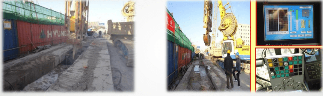
Double wheel milling
When using a milling machine to form grooves, first use a faster milling speed to re-mill the hole dug by the grab to repair the groove section of the grab; when encountering the rock layer, reduce the milling speed to complete the groove formation of the rock layer.
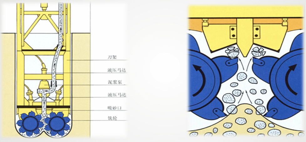
The working principle of the double-wheel slot milling machine is the reverse circulation principle. During excavation, the two milling wheels continuously cut the soil and rocks below, then roll them up and break them into small pieces. They are then mixed with stable mud in the groove and sucked into the pump. The centrifugal pump installed on the vacuum box pumps the mud-containing fragments into circulation equipment, where a vibration system separates the soil and rock fragments from the mud, and the clean mud is pumped back into the tank after treatment recycling.
During the grooving process, various data are collected through the sensor on the milling head, the working status of the two-wheel milling machine is analyzed (the straightness of the milling head, the depth of milling, and the resistance of the milling head), and corresponding operations are performed. Set the descending speed of the milling head according to different soil layers, and control the pressure on the milling head to reduce the wear of the scraper and speed up the groove formation speed. When milling a hard soil layer, the milling head should be lowered slowly (to avoid excessive pressure on the axle at the bottom of the milling head, causing the hard stone to damage the alloy part of the scraper on the axle), and make a small up and down movement to allow the milling wheel to move up The alloy part of the scraper can effectively mill hard soil layers, and broken stones can be sucked away as quickly as possible.
In areas with variable strata, the milling head often causes the front and rear, left and right scrapers to receive different forces when milling, causing the milling head to tilt, thereby causing the slot to deflect. At this time, the operator needs to promptly control the hydraulic jack system to extend or retract the deflection plates installed on the left and right guide plates and the front and rear, adjust the posture of the milling head, and slow down the descent speed of the milling head, thereby effectively controlling the verticality of the slot. Spend.
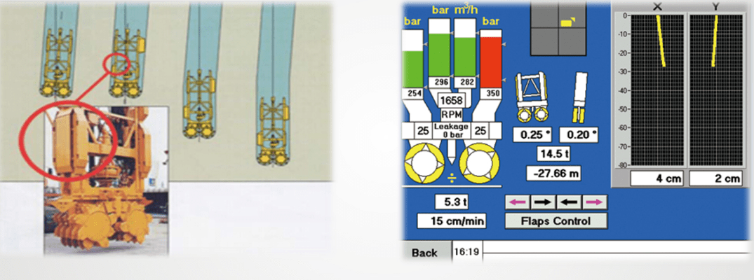
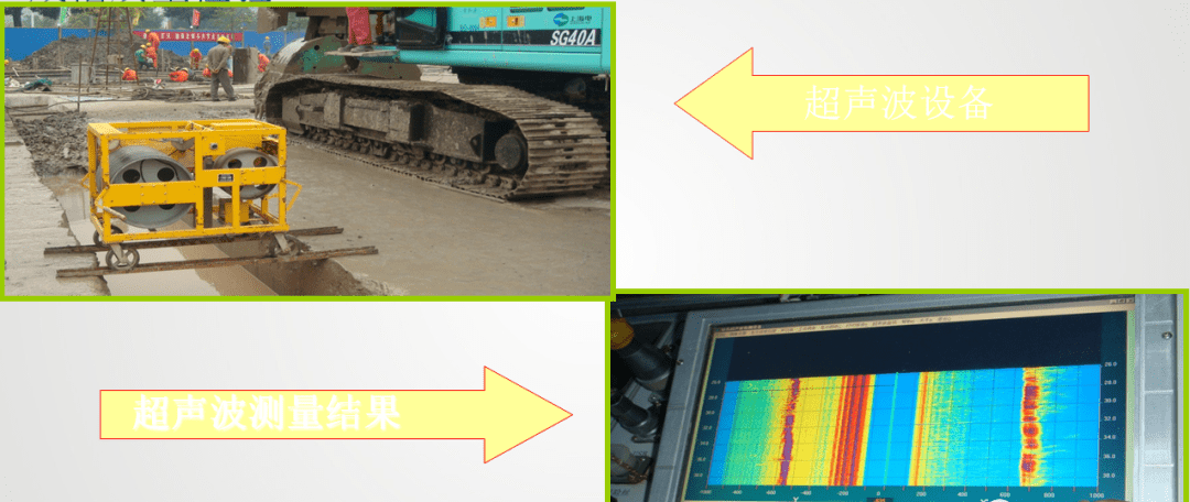
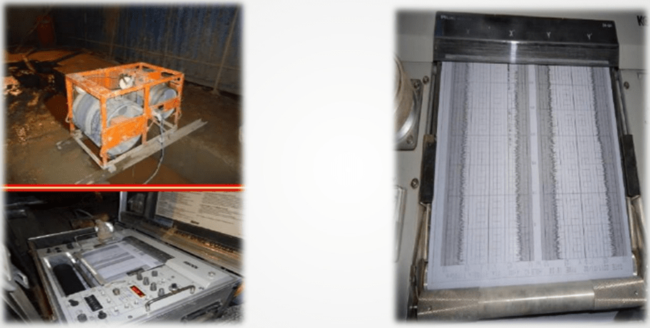
After the final hole is made, the slot hole inspection is carried out. The final hole acceptance items include depth, width, and hole shape, which are measured using ultrasonic logging tools. The ultrasonic logging tool can simultaneously measure and map the hole shape in the X-axis and Y-axis directions, which is fast, convenient, and highly accurate. If the accuracy required by the design is not met, the corresponding processing will be carried out before proceeding to the next process.
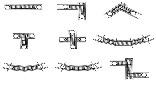
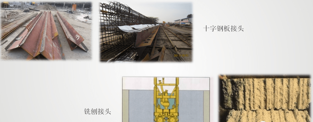
Ground-to-wall connector
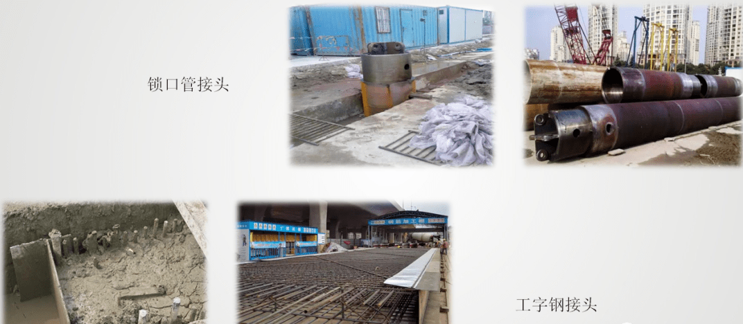
At present, the joint forms that are widely used in China mainly include lock pipe joints, I-beam joints, cross steel plate joints, and milled joints. Each has different construction processes and advantages and disadvantages. According to past construction experience, underground diaphragm wall joints are prone to leakage. The main reason is that the construction joints are not well formed and the concrete is not dense. To give two examples, when using a locking pipe joint, the timing of pulling out the locking pipe joint is closely related to the concrete setting time. If it is too early, the concrete will not be strong enough and will easily collapse; if it is too late, the pullout resistance will be too great and it will be difficult to pull out. During the process, it is easy for the concrete joint section to be damaged, the molding quality is not high, and the concrete is not dense, resulting in water leakage. Another kind of I-beam joint and cross steel plate joint are both rigid joints, which are suitable for strata with poor soil conditions. The waterproof performance is greatly improved compared with the lock pipe. However, the large amount of steel used in construction causes the weight of the ground wall steel cage. It is heavier and the engineering cost is higher.
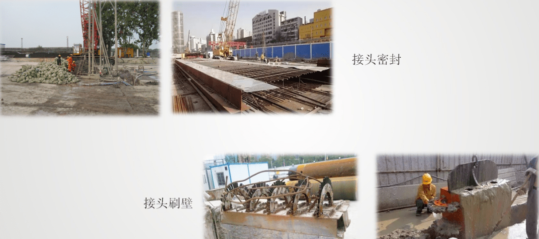
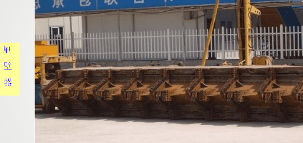
The main construction control point for the above-mentioned joint methods is to prevent the concrete from flowing around the joint. The conventional process is plugging. The plug must be inserted into the bottom, and the backfill behind the plug must be dense. However, from a practical point of view, it is difficult to guarantee the dense filling effect. Although the interface between the new and old tank sections is cleaned multiple times with a wall brush, mud will still be left, causing the concrete there to be loose and leaking.
The construction of joint pipes (boxes) should comply with the following regulations:
1 The joint pipe (box) and connecting parts should have sufficient strength and rigidity.
2 After the joint pipe (box) enters the site and is used for the first time, it should be assembled and tested on-site.
3 The joint pipe (box) should be exposed more than 1.5m~2.0m from the top of the guide wall.
4. The hoisting of joint pipes (boxes) should be lowered vertically and slowly, and the verticality should be strictly controlled.
5 The back of the joint pipe (box) should be filled firmly.
6. The joint pipe (box) starts to be lifted after the concrete is poured and initially set. It is lifted every 30 minutes, 50mm to 100mm each time. It should be completely pulled out before the concrete is finally set.
7. The joint pipe (box) should be pulled out vertically, uniformly, slowly, and continuously, and the concrete at the joint should not be damaged.
8. The joint pipe (box) should be cleaned promptly after being pulled out.
Brushing and cleaning the base
The soil residue left in the trench during the trenching process and the mud scraped off the trench wall when the steel cage was hoisted will accumulate at the bottom of the trench. After the trenching is completed, the soil particles suspended in the mud will gradually settle to the bottom of the trench. Before pouring the underground diaphragm wall, the sediment at the bottom of the tank, which is mainly sediment, must be removed. This work is called bottom cleaning.
There are two basic methods of bottom cleaning: displacement method and precipitation method. The replacement method is to carefully clean the bottom of the trench immediately after digging the trench, and replace the mud in the trench with new mud before the soil residue settles. The sedimentation method cleans the bottom after the soil residue settles to the bottom of the tank. Generally, the bottom is cleaned before or after inserting the steel cage. However, the latter is hindered by the steel cage and cannot be completely cleaned.
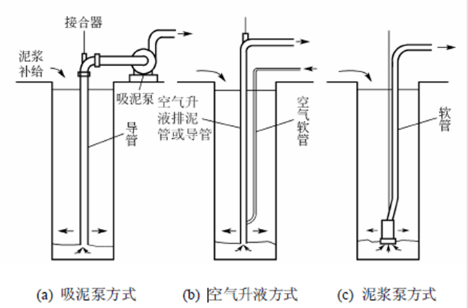
 Methods for removing sediment at the bottom of the tank include:
①Sludge suction pump mud discharge method;
②Air lift liquid mud removal method;
③Sludge discharge method by submersible mud pump with stirring wings;
④Water wheel injection and mud discharge method;
⑤ Grab bucket direct mud discharge method.
Among these methods, the first three are commonly used methods, as shown in the figure.
Requirements for wall brushing and base cleaning
1. After the groove is formed, the end faces of the adjacent sections of concrete should be cleaned and brushed to the bottom. The number of brushing times should not be less than 20 times, and there should be no mud on the wall brushing device.
2. After the wall brushing is completed, base cleaning and mud replacement should be carried out.
3. The pumping method should be used for base cleaning until the sediment and mud.
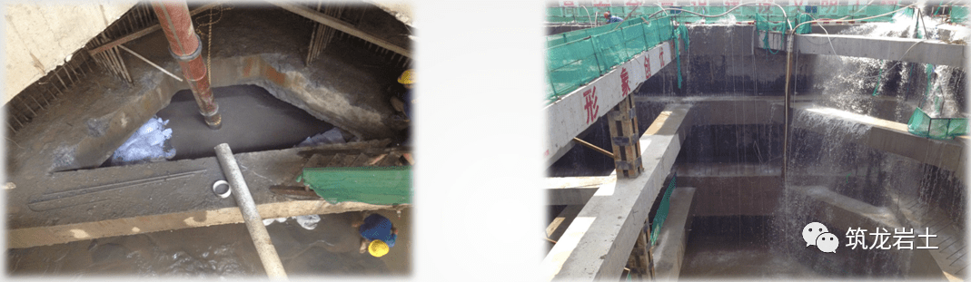
Concrete pouring
1. The conduit should be made of multi-section steel pipes with a diameter of 200mm to 300mm. The connection of the pipe sections should be sealed and firm. A trial assembly and water tightness test should be carried out before construction.
2. The horizontal arrangement distance of the conduit should not be greater than 3m, and the distance from the ends on both sides of the trough section should not be greater than 1.5m. The distance between the lower end of the conduit and the bottom of the groove should be 300mm to 500mm. A water stopper should be placed in the conduit.
3. Pouring underwater concrete should comply with the following regulations:
1) Concrete should be poured in time after the steel cage is hoisted in place, and the interval should not exceed 4 hours.
2) After the initial pouring of concrete, the buried depth of the conduits in the concrete should be greater than 500mm.
3) Concrete pouring should be even and continuous, and the interval should not exceed 30 minutes.
4) The rising speed of the concrete surface in the tank should not be less than 3m/h, and should not be greater than 5m/h; the depth of the duct concrete embedded in the concrete should be 2m to 4m, and the concrete height difference between two adjacent ducts should be less than 0.5m.
5) The concrete pouring surface should be 300mm to 500mm higher than the design elevation. The wall top elevation and wall concrete strength after removing the laitance should meet the design requirements.
6) The pouring area shared by each pipe should be equal.
4. For underground continuous walls with a top drop of more than 3m, low-strength grade concrete or cement mortar should be used to fill space above the design elevation of the wall top, and the remaining groove sections should be filled with sand.
5. The filling coefficient of poured concrete should be 1.0~1.2.
To meet the burial depth of the first pouring conduit and the continuity of subsequent concrete pouring, the supply of concrete must be ensured. The first batch of at least 6 concrete trucks (90m³) must be brought in before pouring can begin. The pouring process is symmetrical.
The spacing between slotted pouring conduits shall not be greater than 3m, and two conduits shall be arranged in the slot section (three sets of conduits shall be arranged in special slots). Each conduit shall be fed evenly, the concrete surface height difference shall not exceed 0.5m, and the buried depth of the conduits shall not be less than 2m and shall not exceed 6m. During the pouring process, according to the calculation of the pouring volume, the concrete surface in the slot is measured every 30 minutes, and the measuring points are set between the two conduits and at both ends of the slot. Simultaneous measurement during pouring.
Wall bottom grouting construction control requirements
1. Grouting at the bottom of the wall should be carried out after the wall concrete reaches the design strength.
2. The grouting pipes should be steel pipes. The number of grouting pipes in a single groove section should not be less than 2. The grouting pipes and steel cages should be firmly fixed. The lower section of the grouting pipe should extend to 200 mm~500 mm from the bottom of the tank.
3. The grouter should use a one-way valve and should be able to withstand hydrostatic pressure greater than 1MPa.
4. The grouting amount should meet the design requirements, and the grouting pressure should be controlled between 0.2MPa and 0.4MPa.
5. After the initial setting of the underground diaphragm wall concrete and before the final setting, high-pressure water should be used to split the grouting pipeline.
6. The grouting fluid should be configured with P.O.42.5 grade cement; the water-cement ratio should be 0.5~0.6; the grouting fluid should be filtered, and the mesh size of the filter should be less than 40 μm.
7. Grouting can be terminated if one of the following conditions is met:
1) The total amount of grouting meets the design requirements.
2) The grouting volume reaches more than 80%, and the pressure reaches 2MPa.
Quality control requirements for underground diaphragm walls
1. Concrete slump inspection should not be less than 3 times for each tank section; there should be no less than one set of compressive strength test specimens for each tank section, and there should be no less than one set for every 100m3 of concrete; the permanent underground diaphragm wall should be tested every Five tank sections should be used as a set of impermeability test pieces.
2. The concrete compressive strength and anti-seepage pressure should meet the design requirements, and the wall should be free of exposed reinforcements and mud inclusions.
The density of the concrete of permanent underground diaphragm walls should be checked using ultrasonic waves, with a total extraction ratio of 20%; core drilling should be used to check the strength when necessary.
Emergency Plan
Develop corresponding emergency plans after the construction of the ground connection wall, mainly when excavation of the foundation pit begins.
◆ Establish an emergency response organization
◆ Emergency supplies and equipment
◆ Emergency rescue
◆ The professional subcontracting team reports the joint leakage, quicksand, piping, and other treatment plans for the floor-to-wall enclosure structure.
Thank You!
