
Overview
Bored piles are constructed by drilling holes into the ground to form a well of specific shape and size. Once the desired depth is reached, a reinforcement cage is lowered into the hole, followed by concrete pouring to form a pile foundation.
Bored Pile Construction Process
1. Construction Preparation
Before drilling, clear the work platform of debris and plan the layout for the drilling rig, reinforcement cage storage, crane positioning, and concrete pouring area. Place sleepers under the rig’s steel pipes to prevent displacement.
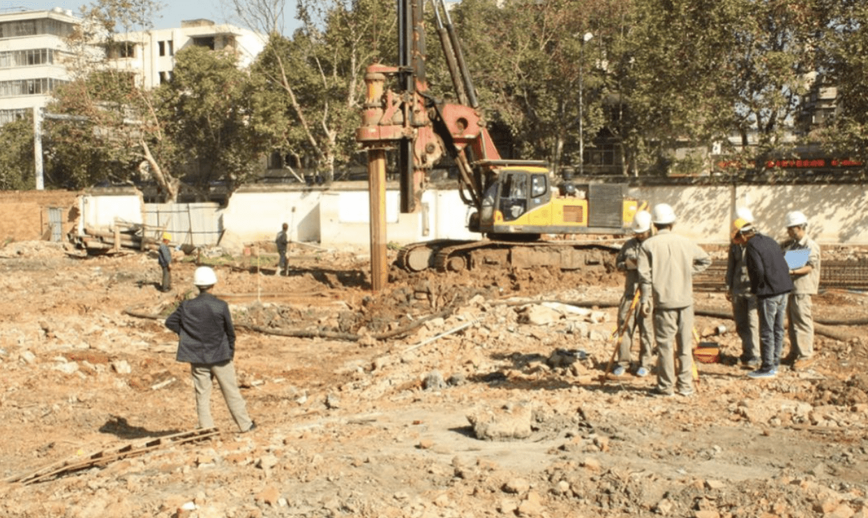
2. Survey and Marking
The surveying team marks the pile center point, and construction crews set up reference stakes. Ensure reference stakes do not interfere with machinery and remain undamaged.
3. Casing Installation
-
Casing diameter should be 30 cm larger than the pile diameter.
-
Use a crawler crane and vibratory hammer for installation.
-
Casing depth depends on site conditions (must penetrate the medium sand layer into the gravel layer).
-
The casing top should align with the platform surface.
-
Center deviation ≤ 5 cm; inclination ≤ 1%.
4. Mud Pit Preparation
-
Use adjacent pile casings as mud pits.
-
Prepare drilling fluid using bentonite (or high-quality loess), caustic soda, and cement.
-
Natural slurry formation occurs through drill bit impact.
Table: Drilling Fluid Performance Indicators
5. Survey Verification
After casing installation, technicians measure the casing top elevation using a level. The surveying team verifies casing alignment.
6. Pile Construction Signboard
Technicians calculate the required drilling depth and record it on the construction signboard.
7. Pre-Drilling Inspection
-
Check if the impact hammer diameter and weight meet requirements (bit diameter should be 80–100 mm smaller than pile diameter).
-
Ensure proper rig positioning (hoisting pulley edge, bit center, and pile center must align vertically with ≤ 20 mm deviation).
8. Drilling
-
Initial drilling should be controlled for stability.
-
Short strokes near the casing edge ensure strong mud wall protection.
-
Normal drilling speed applies only after exceeding the bit height.
-
Maintain drilling logs, collect cuttings, and monitor bit diameter regularly.
9. Reinforcement Cage Fabrication
Table: Allowable Deviations for Pile Reinforcement Cage
10. Hole Inspection
After drilling:
-
Recheck casing elevation and pile length.
-
Measure hole depth using a calibrated rope.
-
Report to quality inspectors for final verification.
Table: Allowable Deviations for Bored Piles (Friction Piles)
11. Primary Hole Cleaning
After drilling, lift the bit 30–50 cm above the hole bottom and flush with high pump volume until parameters meet standards.
Table: Hole Cleaning Qualification Criteria
12. Reinforcement Cage Installation
-
Transport the cage to the site and lower it using a crane.
-
Check hole integrity with a hole detector before cage placement.
13. Reinforcement Cage Positioning
-
Calculate hanging reinforcement length based on casing elevation.
-
Center deviation ≤ 20 mm; top elevation error ≤ ±20 mm.
14. Conduit Installation & Secondary Cleaning
-
Use 300 mm steel conduits for concrete pouring.
-
Conduct water-tightness and tensile tests before use.
-
Maintain 30–40 cm spacing between the conduit bottom and the hole base.
-
Perform secondary cleaning and verify sediment thickness.
Table: Secondary Cleaning Qualification Criteria
15. Concrete Pouring
-
Ensure the first batch volume suffices for ≥1 m conduit embedment.
-
Maintain 2–6 m conduit embedment during pouring.
-
Measure the concrete surface elevation frequently.
-
Pour an extra 0.5 m above the design height for quality assurance.
Formula for Initial Concrete Volume Calculation:
V≥(H1+H2)πD24+πd2h14h1=HWρWρC
Where:
-
V = Required initial concrete volume
-
D = Pile hole diameter
-
H1 = Distance from hole bottom to conduit base
-
H2 = Initial conduit embedment depth
-
d = Conduit inner diameter
-
h1 = Concrete column height balancing external pressure
-
HW = Water/mud depth in hole
-
ρW = Water/mud density
-
ρC = Concrete density
Common Issues & Solutions
1. Hole Collapse
Causes:
-
Impact on hole walls during hammer/cage movement.
-
Shallow casing depth is causing vibration-induced collapse.
-
Inadequate mud level or density.
-
Rapid drilling in sand/gravel layers.
Solutions:
-
Maintain vertical hammer/cage movement.
-
Optimize casing depth based on geology.
-
Maintain mud level above the external water table.
-
Adjust the drilling speed per layer.
-
For minor collapse, increase mud density; for severe cases, fill with clay before slow drilling.
2. Pile Deviation
Causes:
-
Unstable rig or loose components.
-
Poor rig foundation is causing displacement.
-
Uneven resistance from boulders/gravel layers.
Solutions:
-
Calibrate rig alignment and adjust drilling speed.
-
For significant deviation, refill with stone-clay mix and redrill.
3. Slow/No Drilling Progress
Causes:
-
Bit clogging with clay.
-
Poor cutting removal.
Solutions:
-
Enhance cutting removal.
-
Reduce mud density or increase hammer weight.
-
Clean the bit if clogged.
4. Reinforcement Cage Displacement/Deformation
Causes:
-
Excessive cage length without stiffeners.
-
Missing spacers for cover thickness control.
-
Hole deviation or improper cage lowering.
-
Sediment buildup is preventing the design depth.
Solutions:
-
Segment long cages for phased installation.
-
Weld spacers at intervals.
-
Correct hole deviation before cage placement.
-
Ensure thorough sediment removal.
5. Defective Pile Base (“Hanging Pile”)
Causes:
-
Low mud density post-cleaning causes collapse.
-
Incomplete cleaning leaves excess sediment.
-
The wall collapses from the cage/conduit impact.
Solutions:
-
Pour concrete immediately after cleaning.
-
Maintain mud density and internal water head.
-
Avoid wall collisions during operations.
-
Recheck the sediment before pouring.
This structured guide ensures optimal bored pile construction while addressing potential challenges for durable foundation results.
