
Section 1: Construction Preparation and Site Leveling
- Site Preparation
- Complete “Three Connections and One Leveling” (water, electricity, road access, and site leveling) before excavation.
- Remove all obstacles such as underground cables, pipelines, and equipment foundations.
- Ensure temporary facilities (temporary power, water, safety measures) are ready.
- Review Documentation
- Study construction drawings and geological data (soil and hydrogeological conditions).
- Safety Inspection
- Conduct thorough safety checks on cranes and other equipment before operation.
- Site Leveling
- Level the site according to design elevation requirements.
- Clear all obstructions (rocks, tree roots, debris) at pile locations.
- Backfill and compact low-lying areas.
Section 2: Survey and Positioning
- Establish control points using a total station based on coordinates provided by planning authorities.
- Verify points with the client and supervisor before proceeding with axis and pile positioning.
- Use concrete-protected control points to prevent displacement.
- Conduct initial and secondary pile position checks before and after installing guide sleeves.
- Drive a Φ12 positioning rebar as a reference for the drilling machine alignment.
- Verify elevation using a leveling instrument before construction begins.
Section 3: Guide Sleeve Installation
- Installation Requirements
- Center deviation ≤ 20mm, inclination ≤ 1%.
- Made of 4–8mm steel plate, inner diameter ≥ design pile diameter + 200mm.
- Equipped with 1–2 overflow holes.
- Embedment Depth
- ≥ 1.5m in clay, ≥ 2.0m in sandy soil.
- Extend 30cm above ground level.
- Purpose
- Protects the hole opening, guides positioning, isolates surface water, stabilizes slurry level, prevents collapse, and secures the rebar cage.
- Cross-Marking for Alignment
- Set four Φ20 rebar markers in a “+” pattern outside the sleeve for alignment verification.
- Secure markers with concrete and mark them with red paint for visibility.
Section 4: Drilling Rig Positioning
- Place the rig on stable sleepers to prevent shifting.
- Ensure the drill bit center aligns with the guide sleeve (deviation ≤ 20mm).
- Maintain slurry level ≥ 1m above groundwater (or 1.5m in fluctuating conditions).
- Impact Drilling Advantages: Effective in gravel layers, enhances hole wall stability, and improves pile bearing capacity.
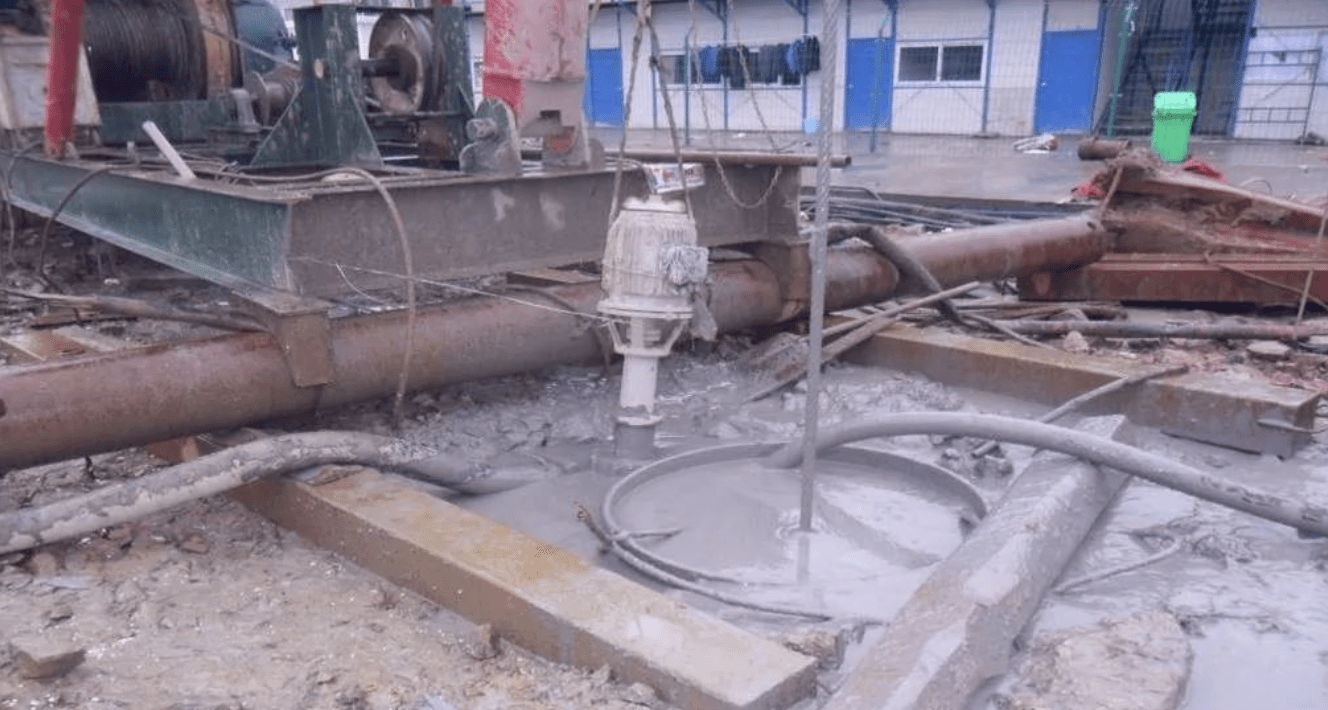
Mud Pump (3PNL-12 Type)
- Critical for slurry circulation during drilling.
- Components: Pump body, impeller, seals, motor, etc.
Section 5: Impact Drilling Process
- Initial Setup
- Fill the guide sleeve with clay and water for slurry formation.
- Slurry Requirements
- Density ≤ 1.25, viscosity 18–20s, sand content ≤ 6%.
- Rock Interface & Final Hole Inspection
- Compare samples with geological reports.
- Confirm the intermediate weathered tuff layer before final approval.
- Drilling Technique
- Start with low-impact (0.4–0.6m height), then increase to 1.5–2.0m after reaching 3–4m depth.
- Check verticality every 1–2m; correct deviations immediately.
Section 6: Primary Slurry Cleaning
- After drilling, circulate slurry to remove sediment.
- Standards: Sand content ≤ 6%, density ≤ 1.25, sediment thickness ≤ 50mm.
- Verify the hole depth before proceeding.
Inspection Tools
- Slurry viscometer, density meter, sediment gauge.
Section 7: Rebar Cage Construction
7.1 Material Inspection
- Verify supplier certifications, test reports, and mechanical properties.
- For seismic zones:
- Tensile-to-yield strength ratio ≥ 1.25.
- Yield-to-standard strength ratio ≤ 1.3.
7.2 Cage Fabrication
- Segment per design, with stiffening rings every 2m.
- Welding: 10d overlap (d = rebar diameter), staggered joints.
- Use spacer blocks (≥3 per section) for concrete cover.
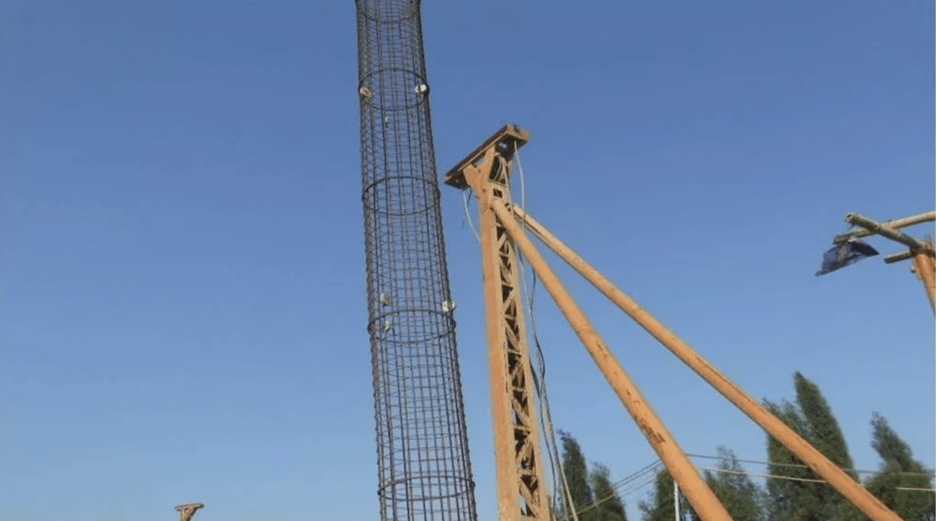
7.3 Installation
- Lift with a crane using dual slings to prevent deformation.
- Align carefully; weld the top support to the guide sleeve.
7.4 Quality Checks
- Length (±100mm), diameter (±10mm), spacing (±10mm main, ±20mm stirrups), verticality (≤1%).
Section 8: Secondary Slurry Cleaning
- Remove post-cage sediment via slurry replacement.
- Final Criteria: Density ≤ 1.25, sand content ≤ 6%, sediment ≤ 50mm.
Section 9: Concrete Pouring
- Method: Tremie pipe with bottom-up displacement.
- Initial Pour: Ensure 1.0–1.3m pipe embedment to prevent slurry intrusion.
- Continuous Pour: Complete within 2–4 hours; no cold joints.
- Monitoring: Maintain 2–6m pipe embedment; measure slump (160–220mm).
Section 10: Key Control Points
- Pile position verification
- Hole depth accuracy
- Rock interface confirmation
- Secondary cleaning
- Rebar quality
- Cage welding & placement
- Initial concrete pour
Section 11: Common Defects & Solutions
11.1 Position Deviation
- Cause: Survey or rig misalignment.
- Fix: Double-check positioning.
11.2 Hole Inclination
- Cause: Unlevel ground or obstructions.
- Fix: Compact soil; clear blockages.
11.3 Necking
- Cause: Collapse or fast pipe extraction.
- Fix: Optimize slurry; control pipe speed.
11.4 Collapse
- Cause: Weak slurry or high water pressure.
- Fix: Use denser slurry; extend sleeves.
11.5 Excess Sediment
- Cause: Soil fall-in or delayed pouring.
- Fix: Clean promptly; pour quickly.
11.6 Cage Float
- Cause: Upward concrete pressure.
- Fix: Secure cage; slow initial pour.
11.7 Pipe Leak
- Cause: Insufficient concrete or broken seals.
- Fix: Ream and repour; check joints.
11.8 Blockage
- Cause: Poor mix or machine failure.
- Fix: Vibrate pipe; use backups.
11.9 Buried Pipe
- Cause: Excessive embedment.
- Fix: Limit to 6–8m; vibrate gently.
11.10 Broken Pile
- Cause: Slurry intrusion or bad concrete.
- Fix: Ensure continuous pour; test mix.
Section 12: Pile Testing
- Methods: Low-strain integrity test, static load test (per JGJ 106-2003).
- Scope: 100% integrity check; ≥1% load tests (min. 3 piles).
