
Section 1: Construction Preparation
Site Leveling
-
Before excavation, ensure the site is fully prepared with access to water, electricity, and proper leveling (Three Supplies and One Leveling).
-
Remove all obstacles such as underground cables, pipelines, and equipment foundations.
-
Set up temporary facilities, including power, water, and safety measures.
-
Review construction drawings and understand subsurface soil and hydrogeological conditions.
-
Conduct safety inspections and tests on cranes and other equipment before operation.
-
Level the site according to design elevation requirements, clearing all debris (rocks, tree roots, garbage, etc.). Fill and compact low-lying areas.
Section 2: Survey and Positioning
-
Establish on-site control points using a total station based on coordinates provided by planning authorities.
-
Verify control points with the client and supervising engineer before proceeding with axis, pile positioning, and elevation control.
-
Protect control points with concrete foundations and warning signs to prevent displacement.
-
Conduct preliminary and secondary pile position surveys before and after installing guide sleeves.
-
Mark pile positions with Φ12 rebar and verify sleeve and ground elevation using a level.
-
Obtain approval from the client and supervising engineer before commencing drilling.
Section 3: Guide Sleeve Installation
Key Requirements:
-
The sleeve must be accurately positioned, with a center deviation ≤20mm and inclination ≤1%.
-
Sleeves are typically made of 4–8mm steel plates, with an inner diameter 200mm larger than the designed pile diameter.
-
Minimum sleeve embedment depth:
-
1.5m in cohesive soil
-
2.0m in sandy soil
-
-
The sleeve top should extend 30cm above ground level.
Functions of Guide Sleeves:
-
Protects the borehole opening
-
Guides drilling alignment
-
Isolates surface water
-
Maintains water head to prevent collapse
-
Secures the reinforcement cage
Cross-Marking for Alignment
-
Set four reference points (Φ20 rebar) in a cross pattern 1–2m outside the sleeve.
-
Secure reference points with 20 cm-thick concrete and mark with red paint for visibility.
Section 4: Drilling Rig Setup
Rig Installation
-
Place the rig on stable sleepers to prevent shifting or tilting.
-
Ensure the drill bit center aligns with the sleeve center (deviation ≤20mm).
-
Maintain mud level 1m above groundwater (1.5m in fluctuating water tables).
Impact Drilling Advantages
-
Suitable for various geological conditions, especially gravel layers.
-
Creates a compacted borehole wall, enhancing stability and load-bearing capacity.
Mud Pump Function
-
Circulates drilling fluid to remove cuttings and supply power to downhole tools.
Section 5: Impact Drilling
Key Steps:
-
Fill the sleeve with clay and water before drilling to form a mud wall.
-
Adjust mud properties:
-
Density ≤1.25
-
Viscosity: 18–20s
-
Sand content ≤6%
-
-
Verify the rock interface and final borehole depth with samples.
-
Start with low-impact (0.4–0.6m height), then increase to 1.5–2.0m.
-
Check verticality every 1–2m; correct deviations immediately.
Section 6: Primary Hole Cleaning
Procedure:
-
After drilling, lower the mud hose to the bottom for circulation.
-
Pump fresh mud to reduce sand content (≤6%) and density (≤1.25).
-
Ensure sediment thickness ≤50mm before proceeding.
Final Hole Inspection
-
Verify hole diameter, depth, verticality (≤1%), and sediment thickness with the client and supervising engineer.
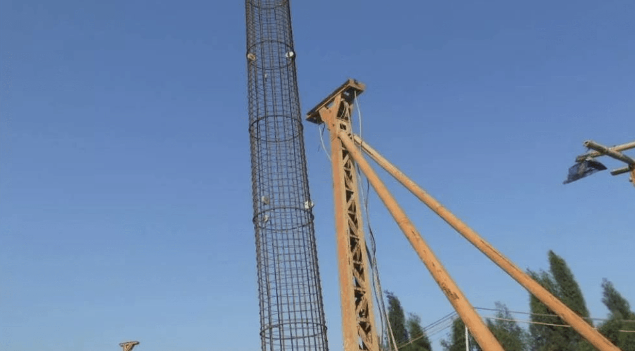
Section 7: Reinforcement Work
7.1 Rebar Inspection
-
Check manufacturer certifications and test reports.
-
Conduct mechanical property tests on samples.
-
For seismic zones, ensure:
-
Tensile-to-yield strength ratio ≥1.25
-
Yield-to-standard strength ratio ≤1.3
-
7.2 Cage Fabrication
-
Weld or bind stirrups to main bars at 2m intervals.
-
Limit joint overlaps to 50% of the total bars per section.
-
Use mortar pads (≥3 per ring) for spacing control.
7.3 Installation
-
Lift the cage with a crane using dual slings to prevent deformation.
-
Align carefully to avoid borehole damage.
-
Secure the top with calculated positioning bars.
7.4 Quality Standards
-
Length tolerance: ±100mm
-
Diameter tolerance: ±10mm
-
Verticality: ≤1%
Section 8: Secondary Hole Cleaning
Purpose:
Remove new sediment after cage/pipe installation.
Method:
-
Use mud replacement with constant pipe agitation.
-
Final checks:
-
Density ≤1.25
-
Sand content ≤6%
-
Sediment ≤50mm
-
Section 9: Concrete Pouring
Critical Controls:
-
Use tremie pipes for underwater placement.
-
The initial pour must cover the pipe end by 1.0–1.3m.
-
Complete pouring within 2–4 hours without interruptions.
-
Maintain pipe embedment depth at 2–6m.
-
Ensure slump: 160–220mm.
Section 10: Key Process Checkpoints
-
Pile position verification
-
Hole depth confirmation
-
Rock interface and final depth approval
-
Secondary hole cleaning
-
Rebar quality approval
-
Cage welding and placement
-
Initial concrete pour
Section 11: Common Defects & Solutions
11.1 Position Deviation
Cause: Incorrect marking or rig misalignment.
Fix: Double-check coordinates before drilling.
11.2 Borehole Tilting
Cause: Uneven ground or underground obstacles.
Fix: Level the site and clear obstructions.
11.3 Necking
Cause: Wall collapse or fast pipe extraction.
Fix: Optimize mud viscosity and control lifting speed.
11.4 Hole Collapse
Cause: Weak mud or excessive drilling speed.
Fix: Use high-quality mud and adjust drilling parameters.
11.5 Excessive Sediment
Cause: Soil fall-in or delayed pouring.
Fix: Clean promptly and pour concrete immediately.
11.6 Cage Floating
Cause: Upward concrete pressure.
Fix: Secure the cage and control the pouring rate.
11.7 Pipe Leakage
Cause: Insufficient initial concrete or faulty seals.
Fix: Remove debris and reseal joints.
11.8 Pipe Blockage
Cause: Poor concrete mix or equipment failure.
Fix: Use vibrators or replace pipes.
11.9 Pipe Burial
Cause: Excessive embedment depth.
Fix: Limit depth to 6–8m.
11.10 Broken Pile
Cause: Concrete segregation or interruptions.
Fix: Ensure continuous pouring and proper mix design.
