
Introduction
With the rapid development of urban construction, land resources have become increasingly scarce, leading to extensive underground development. Deep excavation projects are now commonplace, driving widespread adoption of underground space technology, geotechnical anchoring systems, and complex soil retention techniques. As excavation depths increase and the proximity to existing structures (roads) decreases, ensuring excavation stability, protecting adjacent buildings, and safeguarding construction personnel have become critical challenges.
The high-pressure jet grouting prestressed anchor cable is an innovative earth-retaining structure for soil excavation and slope stabilization. This method addresses challenges such as difficult drilling, incomplete borehole formation, or low drilling efficiency in complex soil conditions. Through extensive research, we have refined this construction technique to deliver superior performance.
Key Construction Features
- Large-Diameter Anchor Body (300-500mm) – Reduces stress concentration in surrounding soil, minimizes plastic deformation, and effectively controls displacement and internal forces through pre-tensioning.
- Enlarged Anchor Head Formation – Achieved through re-mixing and increased grout pressure, this feature enhances pullout resistance by 3-6x compared to conventional anchors, particularly in soft clay.
- Integrated Construction Process – Combines drilling, grouting, mixing, and tendon installation in a single operation, preventing borehole collapse and necking in soft soils.
- Flexible Configuration – Adaptable to constrained sites with adjustable inclination angles, serving as an alternative to conventional soil nails or anchors.
- Superior Performance in Waterlogged/Soft Soils – Prevents borehole instability while ensuring strong soil-cement bonding.
- Active Load Transfer Mechanism – Increases frictional resistance and significantly improves retaining wall performance by controlling soil displacement.
Applications
This method is suitable for:
- Deep excavation support in construction, highway, and hydraulic engineering
- Complex soil conditions
- Excavations adjacent to existing structures
Construction Principle
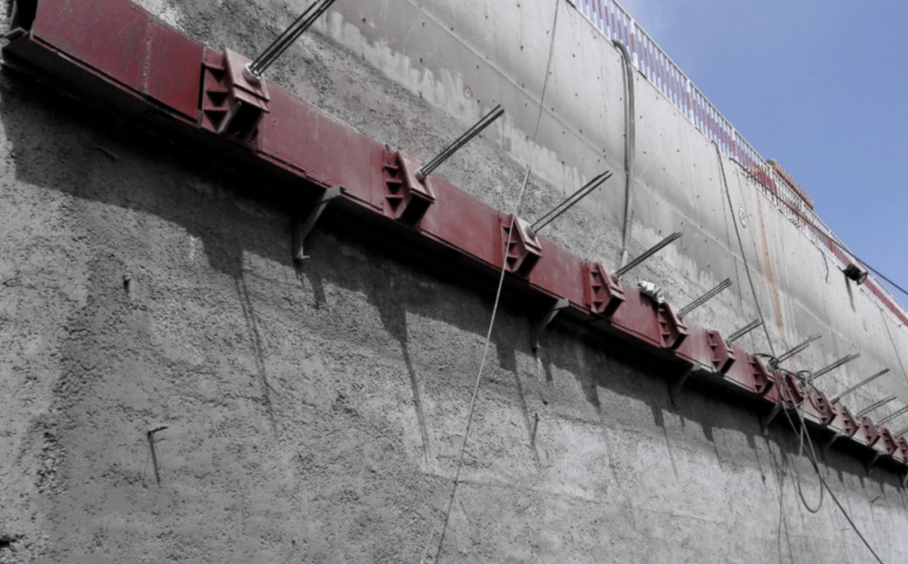
The high-pressure jet grouting prestressed anchor combines large-diameter cement-soil columns with traditional anchor cables. A rotary jet grouting drill forms boreholes at designed angles while injecting cement slurry to create reinforced columns. Simultaneously, the drill head installs steel strands, which are later tensioned to form the completed anchor system.
Construction Process & Key Points
Construction Sequence:
- Excavation → 2. Layout & Marking → 3. Drilling Rig Setup → 4. Angle Calibration → 5. Drilling (with Anchor Installation) → 6. Grouting → 7. Casing Removal → 8. Wale Beam & Anchor Head Installation → 9. Tensioning & Lock-off
Critical Construction Details:
1. Excavation
- Work platform elevation: 1-1.3m below anchor position for equipment clearance
2. Anchor Positioning
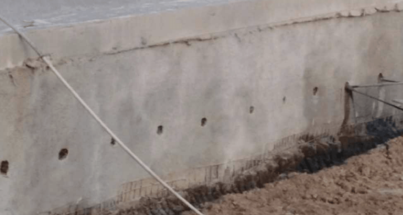
- Clean the retaining wall surface and mark locations within ±50mm accuracy
- Remove 150mm diameter spray-concrete for drill access
- Maintain borehole inclination within ±3°
3. Drilling Rig Setup
- Align the rig using integrated angle measurement (±3° tolerance)
- Ensure a stable platform to prevent movement during operation
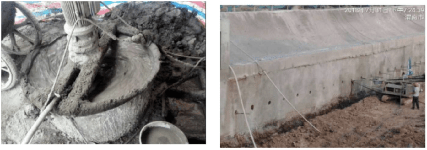
4. Drilling & Anchor Formation
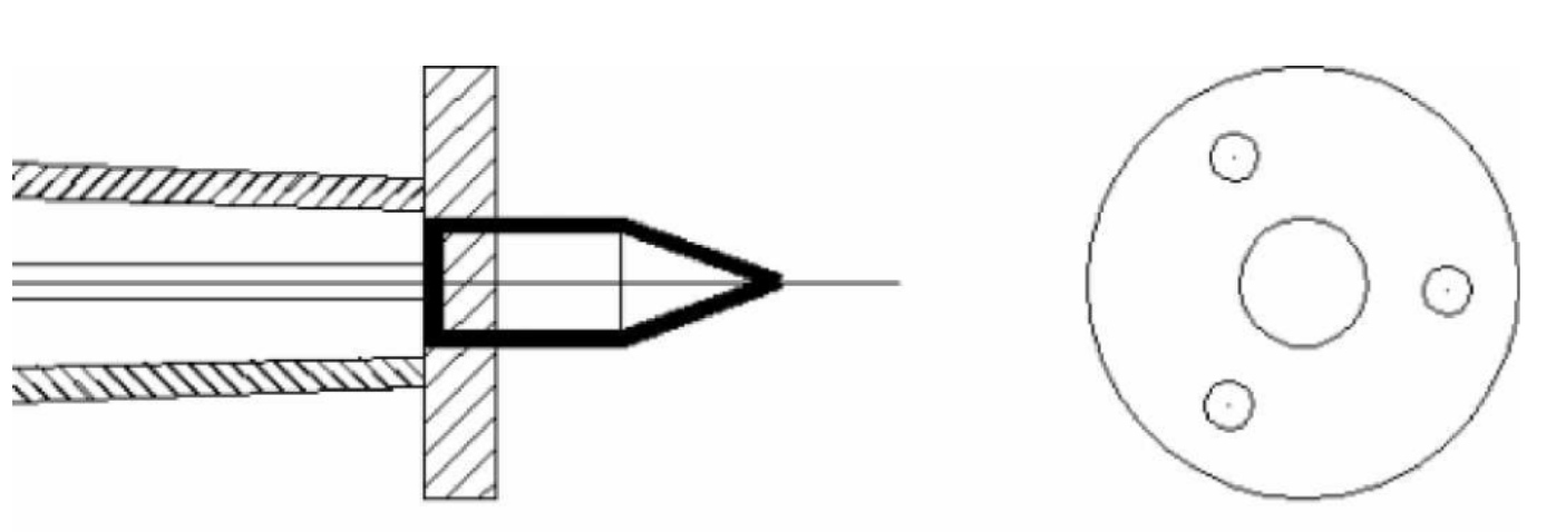
- Use multi-nozzle alloy drill bits for high-pressure rotary cutting
- Maintain borehole length within +0.5m of the design
- Pump filtered cement slurry (≥32.5MPa) through hollow drill rods
- Simultaneous soil mixing during advancement
5. Anchor Cable Fabrication & Installation
- Center steel strands in the anchor body
- Install end plates (Φ150×10mm) with welded nuts
- Leave 0.7m exposed for tensioning
6. Tensioning & Lock-off
- Commence after 10-day curing (80% strength achieved)
- Use calibrated jacking equipment with force-displacement monitoring
- Implement secondary tensioning if significant prestress loss occurs
- Trim excess strands to 30cm post-tensioning

Quality Assurance Measures
Key Control Items:
- Verify borehole depth with dedicated inspectors
- Grout pipe placement: 50-100mm from the hole bottom
- Strict slurry ratio compliance with multiple grout replenishments as needed
General Requirements:
- Material certification & testing for all steel/cement components
- Continuous soil logging with geotechnical verification
- 5% minimum sampling rate (≥3 tests)
Critical Control Measures
- Anchor positioning tolerance: ±5cm
- Rig alignment verification via total station
- Borehole diameter tolerance: ±5cm
- Collapse treatment: Immediate grouting + 24h curing before re-drilling
- Strand preparation: Degreased, straight alignment without
- Length tolerance: ±2cm with proper identification
- Minimum 1cm grout cover maintained during installation
- Continuous grouting during drill withdrawal
- Strict water-cement ratio control
- Tensioning only after the grout reaches design strength
- Pre-use calibration of all tensioning equipment
This optimized construction method delivers reliable performance in challenging geotechnical conditions while meeting stringent displacement control requirements for urban excavation projects.
