
Introduction to Long Spiral Drilling Grouting Piles
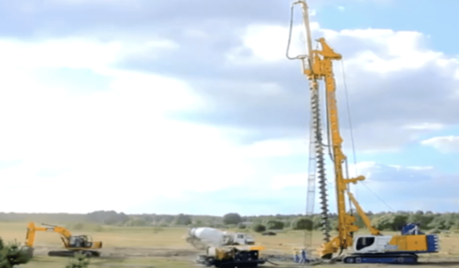
Long spiral drilling grouting piles are an innovative foundation construction method widely used in engineering projects. This technique offers strong adaptability to geological conditions, fast pile formation, low noise pollution, and cost-effectiveness.
Construction Process
01. Reinforcement Cage Fabrication
- Material Preparation & Fabrication:
- Based on design drawings, calculate cutting lengths and prepare a cutting list.
- Fabricate main bars, stiffening rings, and spiral stirrups in the processing area.
- Mark the main bar positions on stiffening rings and fix them via spot welding.
- Spiral stirrups are wound continuously from the pile tip upward and secured by spot welding.
- Main Bar Connection:
- Use threaded couplers for main bar connections, ensuring exposed threads ≤2P.
- Quality Inspection:
- Complete quality inspection forms and obtain approval from the quality control engineer before use.
02. Surveying & Layout
- Steps: Preliminary site selection → Measurement plan → Instrument calibration → Control network setup → Construction surveying → Data recording & organization.
- Key Requirements:
- Surveyors and engineers must cross-verify calculations before staking.
- Use a total station for precise positioning, with allowable deviations:
- Group piles: ≤20mm
- Single-row piles: ≤10mm
- Mark pile centers with lime circles for guidance.
03. Drilling Depth Control
- Monitor depth using drill rod markings.
- Stop drilling upon encountering adverse geological conditions or obstacles and take corrective measures.
04. Pre-Drilling Inspection
- Verify drill tool length, spiral blade diameter, ground elevation, and mast verticality (≤1% of pile length).
- Ensure the drill bit aligns with the pile center.
- Issue a drilling notice specifying:
- Ground/pile top elevation
- Pile diameter, drilling depth, and rock penetration depth
- Reinforcement cage details
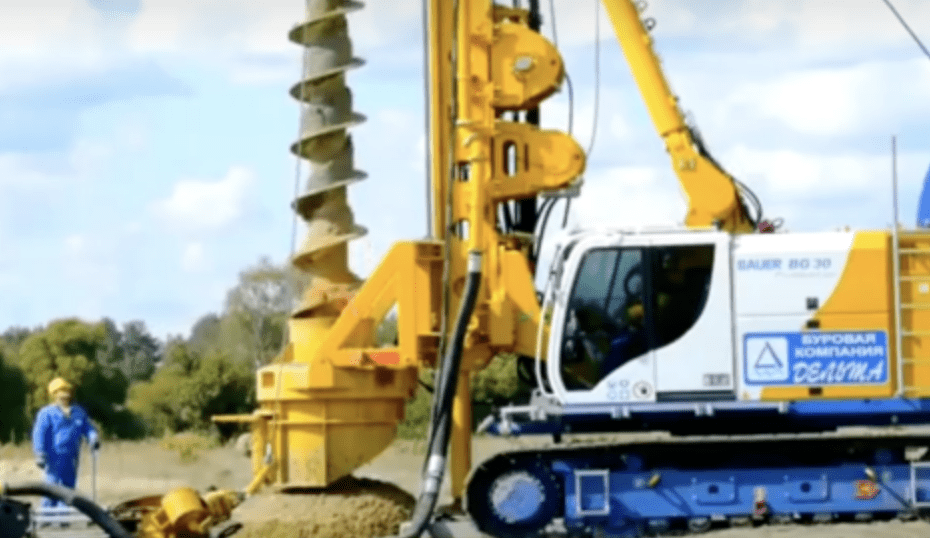
05. Drilling Execution
- Positioning: Align the drill bit within 20mm of the designated point.
- Verticality Control: Use dual plumb bobs for accuracy.
- Drilling Parameters:
- Initial penetration: Slow speed with a closed bit.
- Avoid reversing/raising the drill rod during operation.
- Test drilling required for hard clay, thick sand, gravel, or high-plasticity soil (Ip>25).
- Normal speed: 1–1.5 m/min.
- Obstacle Handling: Halt drilling if jamming or machine instability occurs.
- Spoil Removal: Excavate and transport soil promptly to maintain a clean site.
06. Final Hole Inspection
- Confirm depth meets design requirements via drill rod markers.
- Proceed to concreting only after approval.
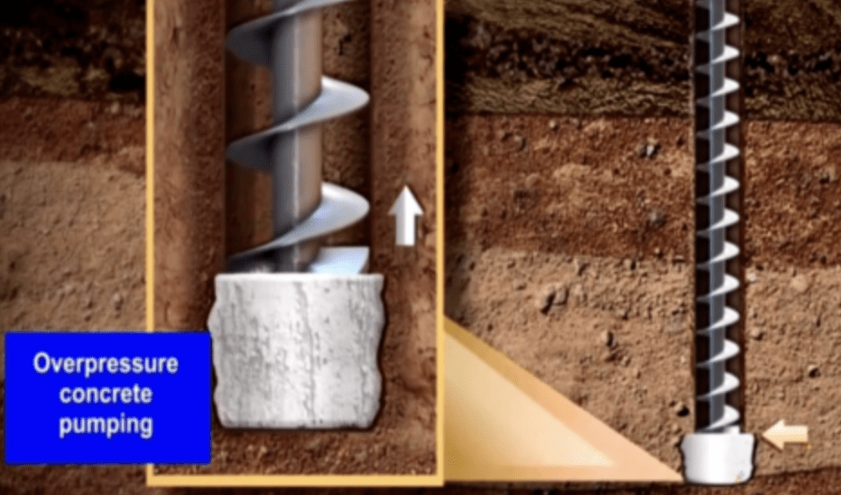
07. Concrete Pouring & Drill Rod Extraction
- Concrete Requirements:
- High workability (slump: 180–220mm) for pumpability and cage insertion.
- Pump pressure: ~30kPa to force concrete through the hollow drill rod.
- Key Steps:
- Stop rotation and pump concrete to open the check valve.
- Maintain upward pressure as the rod rises, ensuring full hole filling.
- Overfill to create a 0.5 m+ “virtual pile” (target expansion coefficient: 1.2).
- Quality Controls:
- Minimize pipe bends for smooth pumping.
- Continuous pumping with ≥40cm concrete in the hopper to prevent airlocks.
- Match lifting speed to pumping rate (≤2.5 m/min).
- Clean the spoil promptly during extraction.
- Sample concrete per GB50202-2018 (1 test/100m³ or 12-hour interval).
09. Reinforcement Cage Installation
- Integrated Process: Insert the cage immediately after concreting.
- Placement Method:
- Use a 5T winch + 200-type excavator to lower the cage.
- Ensure 50 cm+ overpour to prevent soil ingress.
- Verticality Check: Deploy dual plumb lines for alignment.
- Insertion Protocol:
- Initial sinking by gravity, followed by vibratory hammer (speed: 1.2–1.5 m/min).
- Vibrate briefly at a final position to enhance concrete compaction.
10. Curing
- Protect pile heads with plastic film + 800mm soil cover to prevent cracking from rain/sun.
Critical Construction Notes
- Pile Length: Ensure effective length ≥ design via geological reports and real-time monitoring.
- Concrete Specifications:
- Slump: 180–220mm; max aggregate size: 30mm.
- Admix fly ash/additives as needed.
- Post-Drilling: Pump concrete first, pause 10–20s, then lift slowly.
- Waterproofing: Seal drill rod valves in water-bearing sand layers.
- Overpour: Always maintain ≥0.5m excess concrete at the top.
This optimized construction process ensures high-quality, durable, long spiral drilling grouting piles while adhering to industry standards and enhancing site efficiency.
