
[Abstract] Rotary drill is a pile foundation construction machine with a high degree of mechanization and intelligence, flexible walking and movement, and simple installation and alignment. With different drill bits and construction techniques, it can realize hole-forming operations in different strata, and its applicability is Strong; fast drilling speed, high construction efficiency; less pollution, less vibration, less noise during operation, energy saving and environmental protection, low construction cost, economical and reliable. This article combines the construction of the Doubu River tributary bridge and briefly discusses the construction of rotary drilling in the pebble layer, to provide a reference for the construction of similar types of pile foundations.
【Key words】rotary drill, pebble layer
I. Introduction
At present, rotary drilling rigs are widely used in the foundation construction of roads, bridges, docks, high-rise buildings, etc., and are the first choice for large-diameter and deep-pile foundation projects. Rotary drilling rigs can be equipped with a variety of drill bits, with a maximum drilling diameter of 3 meters, a maximum depth of 120 meters, and a maximum drilling torque of 620knm.
With the vigorous promotion and application of rotary drilling rigs in my country in recent years, rotary drilling rigs are designated for use in more and more construction projects in domestic pile foundation construction. Although rotary drilling rigs have so many advantages, as far as current domestic rotary drilling rigs are concerned, if there is no correct construction method for pebble formations, then rotary drilling rigs will not have any advantages over traditional impact drills. The key to rotary drilling construction lies in which machine model to use, what drilling tools to use, and how to choose the correct construction method. Therefore, based on the Doubu River Branch Bridge, the construction plan of rotary drilling in the pebble layer was studied. As far as this project is concerned, rotary drills not only play a very important role in ensuring project quality and reducing project costs. At the same time, if a more reasonable construction plan can be summarized for the construction of rotary drills, it will be beneficial to the company’s future similar projects. The project will surely serve as a good reference and guidance.
2. Construction principle
The rotary drilling rig is a multi-functional, high-efficiency drilling equipment for cast-in-place pile holes. It can realize automatic vertical adjustment of the mast and measurement of drilling depth. For different strata, the rotary drilling rig is used with different types of drill bits to use the drill bit. The rotation of the rod (the drill rod is a multi-section telescopic structure) and the drill bit uses the drill bit’s weight and hydraulic pressure as the drilling pressure, and the hole is formed through repeated cycles of the drill bucket’s rotation, drilling, lifting, and slag discharge.
For formations with low strength, rotary drilling rigs rely on the dead weight of the drill pipe drill bit and the bucket teeth to cut into the soil and rock layer when the drill pipe rotates. The oblique bucket teeth cut off the soil and rocks when the drill bit rotates and push them into the sand bucket to complete drilling. To collect soil; if you encounter strong rocks, the rotary drill can be equipped with other drill bits. First, pressurize the drill pipe through the pressurized oil cylinder, forcibly cut the bucket teeth into the rock, crush the rock, and then replace the sand bucket and rotate it. The drilling rig is equipped with a sand fishing bucket. The power head rotates the bottom door of the bucket drill bucket with bucket teeth to cut the rock and soil, and the undisturbed rock and soil are loaded into the drill bucket. Then the drill bucket is lifted out of the hole by the drill winch and telescopic drill rod. Unload soil, and repeat this cycle, continuously taking in soil and unloading soil until the drill reaches the designed depth.
3. Construction process and operating points
3.1 Process flow diagram
3.2 Construction points
3.2.1 Hydrogeological research
According to geological survey and drilling revelations, the bridge site area is slightly dense to medium dense pebbles above 7.00m, strongly weathered from 7.00 to 19.00m, moderated mudstone from 19.00 to 53.70m, moderated sandstone from 53.70 to 65.70m, and moderately weathered sandstone from 65.70m to 65.70m. The depth beyond 90.70m is weathered mudstone, and the rock formation shape is 290°∠45°. The groundwater on the site is mainly pore water in the pebble layer. The pebbles have good water permeability and abundant water.
3.2.2 Rotary drilling rig selection
(1) Drilling rig selection
Given the large pile diameter of the pile foundation of this project and the various geological conditions on site, ordinary rotary drills cannot complete the drilling work. Therefore, through comparison and selection, the SR360 rotary drilling rig of Sany Heavy Industry was finally selected.
(2) Drill pipe parameters
The drill pipe adopts a machine-locked drill pipe (φ580 piece set) with a length of 4*17m.
(3)Drilling tool parameters
Seven types of drill bits are used, including a φ2.5m barrel drill and a rock-embedded double-bottom sand fishing drill bucket (equipped with a pick bit), a φ2.5m sand fishing drill bucket (equipped with shovel teeth), and a φ1.8m sand fishing drill bucket (equipped with a pick bit). shovel teeth), φ1m barrel drill (with pick drill), φ1.8m barrel drill (with pick drill), φ2m barrel drill (with cone drill).
3.2.3 Site leveling
Rotary drilling construction requires that the site foundation be flat and solid, equipment operations must be unobstructed, and maintenance, slag removal, and drilling operations must not interfere with each other. At the same time, prepare a certain number of steel plates to pave the way according to the actual construction geology of the site to ensure that the drilling rig is flat and firm during the entire construction process.
3.2.4 Measurement and Setting Out
Use a total station and according to the drawings, lay out the pile positions, nail the steel bars at the set pile positions, and nail the steel bars around the pile positions with the steel rods as the center and protect them well.
3.2.5 Drilling rig in place
When the drilling rig is in place, check whether the performance of the drilling rig is in good condition in advance to ensure that the drilling rig is working properly.
Drive the rotary drilling rig to the construction position, determine the luffing position of the drilling rig and the forward or backward tilt of the chassis according to the pressure requirements, hole depth, and soil unloading convenience, adjust the mast angle, operate the winch, and align the drill bit center with the drilling center Align and adjust the verticality parameters of the drill rig to make the drill pipe vertical, while slightly lifting the drill tool to ensure that the drill bit ring cutter floats freely. Rotate the drilling rig back and forth to check whether there is any interference during the construction process (rotation interference, interference with the drilling slag truck), whether it is convenient to remove the casing, and whether it is convenient to replace the drill bit. Determine the accidents that may be encountered during construction based on the geology. If there is an accident, it is easy to handle. In short, when the equipment is in place, issues such as construction effectiveness, construction convenience, and accident handling feasibility must be considered.
At the same time, the installation of the hydraulic multi-functional rotary drilling rig must be stable, and necessary drilling rig fixing measures must be taken on the platform to ensure that the drilling rig does not shift during the drilling process. When the drilling rig is in place, the maximum inclination angle with the plane shall not exceed 4°.
Before drilling, the drilling rig uses a total station or theodolite to adjust the mast angle. The drilling rig operator determines the system error based on the data in the adjusted electronic display and makes adjustments during subsequent construction to ensure the verticality of the drilling rig.
3.2.6 Buried steel casing
Burying the casing under the premise of accurate setting out should comply with the methods and requirements for burying the casing. The drilling in this project is carried out on land, and the pit digging method is generally used, which is relatively simple and easy to implement.
The embedding of the steel casing is the beginning of the construction of the rotary drilling rig. The plane position and verticality of the steel casing should be accurate, and the periphery of the steel casing and the casing feet should be tight and impermeable.
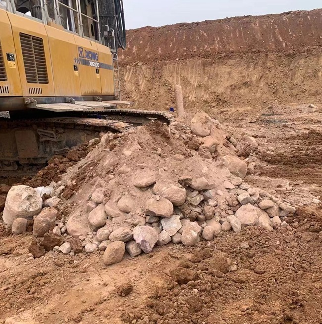
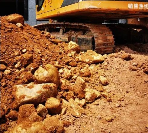
The 5 to 7-meter pebble layer on the surface of the pile foundation of this project is a severely permeable stratum. If the casing is buried after being excavated by an excavator, the casing will easily collapse because the size of the excavator is large. Therefore, in this project, a rotary drill equipped with a 2.5-meter drill bit was used to directly expand the hole (to a hole with a diameter of 3 meters), and then a 2.8-meter steel casing was buried with a casing length of 3 meters.
After the casing is buried, ensure that its plane position deviation is not greater than 50mm and its inclination is not greater than 1%. The upper mouth of the casing should be no less than 0.3m above the ground. The purpose of being higher than the ground is to prevent ground debris and people from falling into the hole, and to follow the casing when the blade foot is perforated.
3.2.7 Mud preparation
Since holes drilled by rotary drilling are not easy to form mud skin, the wall protection is relatively poor, and it is easy to shrink the diameter and collapse the hole. Therefore, rotary drilling requires relatively high mud preparation requirements.
The mud is made by mixing water, bentonite, soda ash, and carboxymethyl cellulose (CMC). After the mud is stirred in the mud pool with a mixer, it is pumped into the hole. The rotary drill drills evenly and slowly, and the mud acts as a wall protector. role.
The mud preparation ratio is: water: bentonite: cellulose: soda ash = 1000: (60~80): (1~1.5): (2~2.5). The performance index of the prepared mud should meet the following standards: the pulping capacity is not less than 2.5L/kg, the sand content of the produced mud is no more than 4%, the colloid rate is no less than 95%, the viscosity is controlled at 26s~32s, the specific gravity is 1.08~1.12, and the pH value is greater than 8 and less than 11.
3.2.8 Construction Difficulties
Since the pebble layer in the geological layer of this project is relatively thick, the casing may easily collapse if the construction is unreasonable.
Therefore, the following situations should be carefully considered before construction: how to drill effectively, how to drill efficiently, how to prevent construction accidents, how to deal with construction accidents, how to operate, what kind of drill bit to choose, how to modify the drill bit according to the stratum, how to use mud and casing etc.
3.2.9 Drilling method
During the drilling process, the verticality of the drill pipe is ensured through electronic control (the drilling rig is equipped with an electronic control display system) and manual observation, thereby ensuring the verticality of the hole. At the same time, the drilling depth is controlled by the depth counter. When the rotary bucket drill bit rotates clockwise to drill, the cutting plate of the bottom plate is aligned with the rear edge of the cylinder flap. Drilling cuttings enter the barrel and after one bucket is filled (generally filling 2/3 of the bucket is more appropriate, more accidents of buried drilling and muddy drilling will occur, and less will be detrimental to the progress and cost), the drill bit rotates counterclockwise, and the bottom plate is Position the positioning block and seal the opening at the bottom, and then lift the drill bit to the ground to unload soil.
When drilling begins, low-speed drilling is used, and the wire rope of the main winch bears no less than 20% of the weight of the drill pipe and drilling tools to ensure that there is no deviation in the hole position. The drilling speed can be increased after drilling 3m below the bottom of the casing.
Drill bits are the drilling tools used by rotary drilling rigs. Drill bits have defects. Even drilling rigs with superior performance cannot play their role, which directly affects efficiency, increases component wear and consumption, and thus increases production costs. Therefore, during the drilling process, pay attention to the drilling methods of different formations and consider whether the drill bit can be replaced.
When drilling into the pebble layer, this project uses a 2.5-meter shovel tooth sand bucket, combined with a 2.5-meter pick rock-embedded sand bucket. However, because the cutting area of the shovel teeth is relatively large, the use of shovel teeth is more conducive to construction.
During the drilling process, the progress should be measured at certain intervals and recorded, and the drilling record form should be filled in. At the same time, attention should be paid to recording damage to mechanical equipment and other conditions.
3.2.10 Construction characteristics
(1) During the construction of the pebble layer, the surrounding areas of the casing must be compacted, so as to avoid accidents such as overturning of the drilling rig caused by large-scale collapse of the casing during construction. At the same time, the drill bit should be raised and lowered steadily to avoid hitting the hole wall and causing the pebble layer to collapse.
(2) Before drilling, the drill bit diameter protection device, drill bit diameter, and drill bit wear must be checked. During the construction process, drill bit wear exceeding the standard must be replaced promptly.
(3) During the hole formation, the construction shall be carried out according to the parameters determined by the trial construction. A full-time recorder shall be appointed to record various parameters of the hole formation process, such as drilling depth, geological characteristics, mechanical equipment damage, obstacles, etc. Records must be careful, timely, accurate, and clear.
(4) The rotary drilling rig is equipped with an electronic control system to display and adjust the verticality during drilling. Before construction, the verticality of the drill pipe must be ensured through electronic control and manual observation to ensure the verticality of the hole.
(5) When drilling with a rotary drilling rig, pay attention to the control of footage while drilling. When using a rotary digging bucket, depending on the capacity of the bucket body, generally two-thirds of the bucket body is suitable. The depth of footage is determined based on the diameter of the pile, and the depth of footage should also be controlled based on the density of the formation. Excessive footage will make it difficult to unload soil, and may also lead to accidents in which buried drills become stuck. Too little will delay the construction progress and consumption of equipment and energy, increase costs, and reduce benefits.
(6) Pay attention to the water head difference in the casing to avoid moving the rotary drill up and down the drill bit, causing mud surge and damaging the bottom edge of the casing.
(7) There should be no foreign objects at the bottom of the hole. If there are fallen objects, they must be salvaged in advance. Otherwise, the drill bit will easily collapse or fail to fully contact the rock surface, causing the drill bit to fail.
3.2.11 Prevention and treatment of common diseases in the pebble layer
(1) Water leaking from the outer wall of the casing will cause the foundation to sink, and the casing to tilt and shift in severe cases, causing the pile hole to deflect and even make construction impossible.
Cause analysis: The buried casing is not dense to the surrounding soil, the water level difference in the casing is too large, or the drill bit collides when it rises and falls. Preventive measures: When burying the casing, drill soil with the best water content should be used at the bottom and around the pit and tamped in layers to open the casing at an appropriate height, so that a certain water head height is maintained in the casing to prevent collision with the casing when lifting the drill bit.
When water is found escaping from the casing, drill soil can be used to fill and reinforce the surrounding area. If the casing seriously sinks or shifts, it should be reworked and reburied.
(2) Drilling is extremely slow or no footage is drilled.
Cause analysis: Improper selection of drill bits, improper installation angle of alloy cutting tools, cutting soil too shallowly by cutting tools, too light counterweight of drill bits, and filling the drill bits with drilling soil.
Preventive and control measures include replacing or modifying the drill bit, rearranging the angle, shape, and arrangement direction of the tool, increasing the counterweight, strengthening slag discharge, reducing the specific gravity of the mud, or switching to drilling methods.
(3) The wall of the pile hole collapses into the hole or collapses to varying degrees after the hole is formed. Bubbles constantly appear in the mud discharged from the hole, and sometimes the water level in the casing suddenly drops, which are precursors of hole collapse.
Analysis of the cause is mainly due to the loose pebble layer, poor mud wall protection, poor casing burial, low water level in the barrel, lifting the drill bit and drilling too fast, or idling for too long, which can easily cause the lower part of the borehole to collapse or The waiting time and filling time after the hole is formed are too long.
Preventive and control measures include burying the casing appropriately deep in the pebble layer, backfilling the soil densely, using high-quality mud, increasing the specific gravity and drillability of the mud, raising the casing, replenishing the casing after the final hole, maintaining the required water head height, and ensuring the quality of the steel cage. When hoisting to prevent deformation, aim at the hole position, lift straight and steady, and sink slowly to prevent collision with the hole wall. The time for pouring after the hole is formed should generally not exceed the time, and the pouring speed should be accelerated as much as possible, and the pouring time should be shortened before the steel cage is drilled. If the hole is inside, backfill with a mixture of slurry, sand, and clay to one depth above the collapsed hole, or backfill and compact the entire hole, then use the original drill bit and high-quality mud to sweep the hole. In the case where the steel cage hits the hole wall and causes a slight collapse, use a drill bit with a diameter smaller than the inner diameter of the steel cage to sweep the hole with high-quality mud or use a catheter to clear the hole.
4. Advantage analysis
4.1 When using a rotary drilling rig for construction, fewer construction workers are required than an ordinary drilling rig. The rotary drilling rig can move freely and does not require lifting equipment for lifting and transportation, which can save a lot of personnel and supporting machinery.
4.2 If general impact drilling is used in this project, it is necessary to add a first-level distribution transformer and power circuit and cable laying in the site. The rotary drill uses a diesel engine to provide power independently, saving a lot of off-site and on-site supporting equipment.
4.3 The hole expansion coefficient of rotary drilling is very low, generally below 1.02, while the hole expansion coefficient of general impact drills is above 1.07. This can save a lot of concrete.
4.4 The hole-forming speed of a rotary drill in the pebble layer is generally 2m/h, which is about three times the speed of an ordinary drilling rig. The use of rotary drills greatly shortens the construction period.
Thanks
