
Introduction
The underground diaphragm wall is a critical structural element used in deep excavations, tunneling, and foundation engineering. This article details the construction methodology, quality control measures, and inspection techniques for underground diaphragm walls, optimized for SEO and readability.
Primary Construction Methods
1. Engineering Survey
- Elevation Control: An S3 level is used to transfer elevation benchmarks to the construction site. Control points are verified before use.
- Alignment: A J2 theodolite establishes the diaphragm wall centerline based on design drawings. Regular verification ensures accuracy.
- Periodic Checks: Control points are rechecked every two weeks to maintain precision.
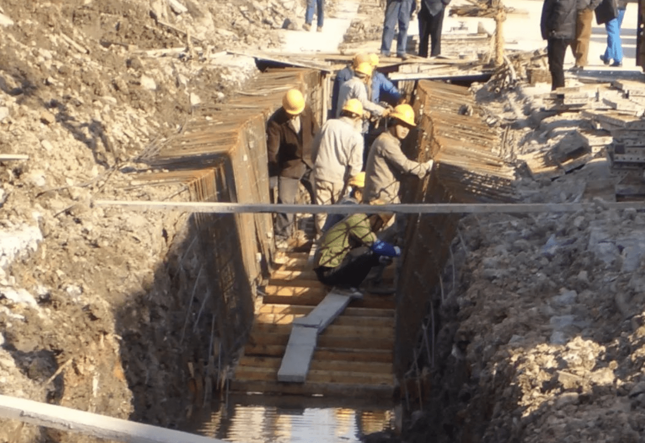
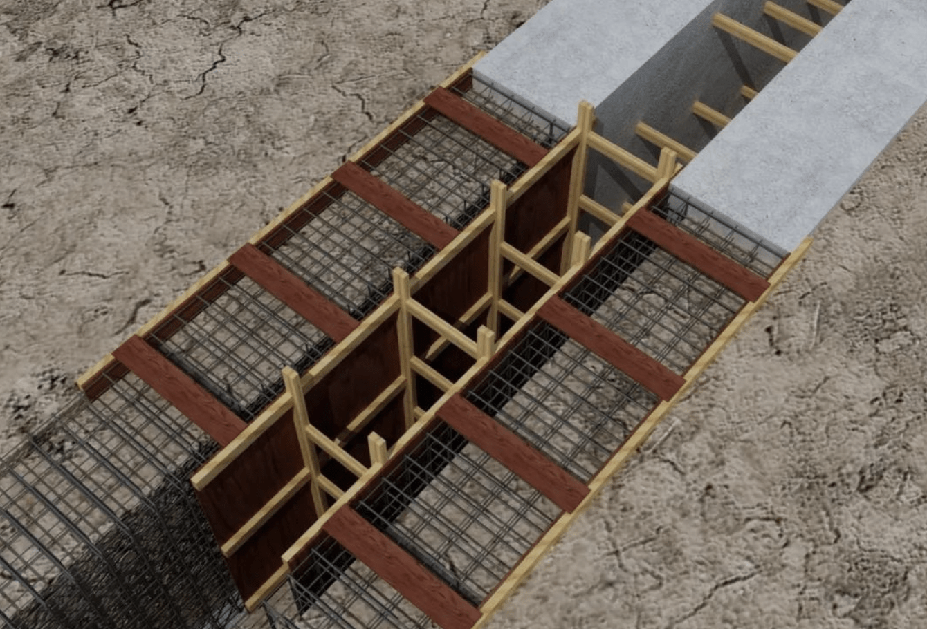
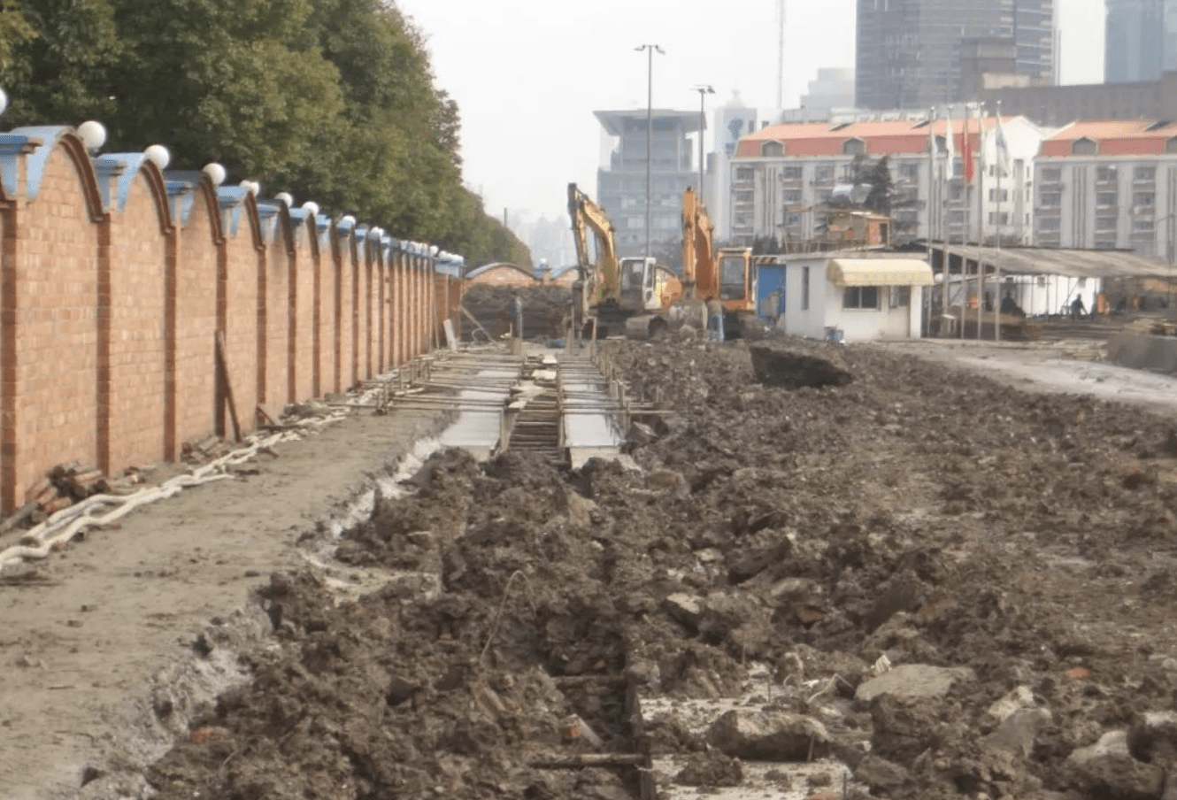
2. Guide Wall Construction
Functions of Guide Walls
- Provides alignment for trenching equipment.
- Maintains slurry levels and stabilizes the upper soil.
- Prevents soil collapse during excavation.
Construction Sequence
- Site Preparation: Leveling, surveying, and trench excavation.
- Formwork & Reinforcement: Wooden formwork and steel reinforcement installation.
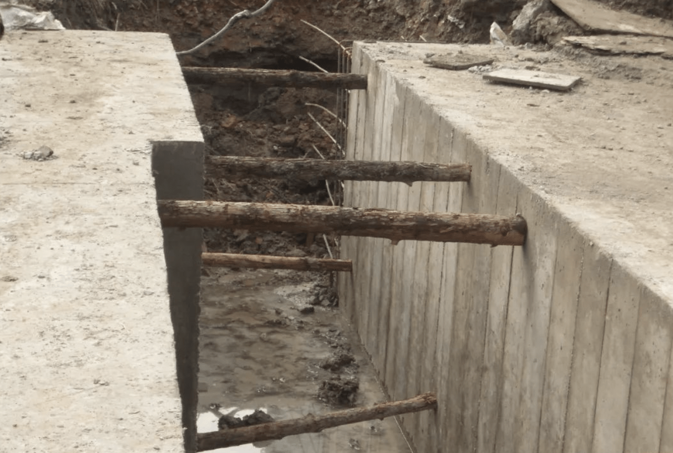
- Concrete Pouring: C20-grade commercial concrete is used with vibratory compaction.
- Curing & Backfilling: Supports are added to prevent deformation, followed by backfilling.
3. Slurry Technology
Slurry Mix Design
- Composition: Bentonite, CMC, dispersants, and water.
- Properties: Density ≤1.20, stability, and low filter loss.
- Testing: Lab trials optimize mix ratios for soil conditions.
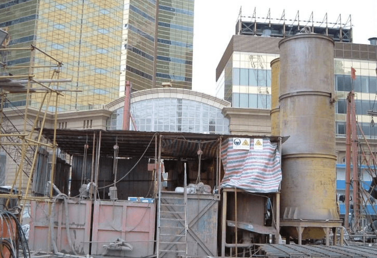
Slurry Recycling System
- Equipment: Mixers, storage tanks, pumps, and vibrating screens.
- Treatment: Sedimentation and chemical treatment for reuse; deteriorated slurry is discarded.
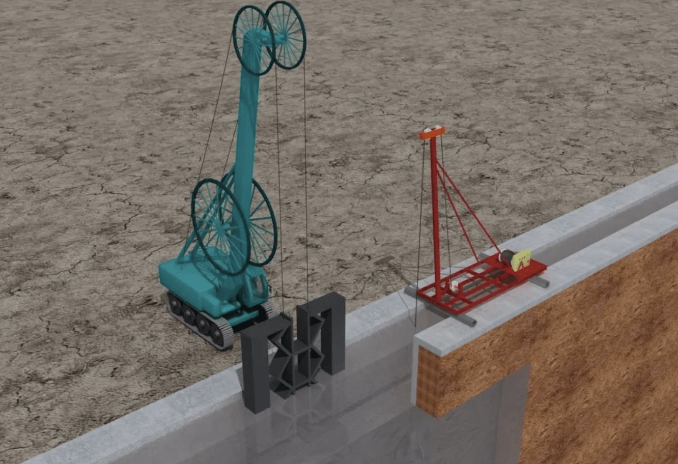
4. Trenching
Excavation Process
- Pilot Holes: Rotary drills create guide holes for grab buckets.
- Verticality Control: Ultrasonic monitoring ensures <3‰ deviation.
- Debris Removal: Grab buckets clean the trench bottom.
Quality Checks
- Depth & Alignment: Measured via plumb bobs and ultrasonic scanners.
- Acceptance Criteria: Wall verticality, flatness, and depth must meet specifications.
5. Joint Treatment
I-Beam Joints
- Cleaning: Impact hammers and scrapers remove debris from joints.
- Filling: Sandbags and foam prevent concrete seepage.
- Inspection: Wire brushing verifies joint cleanliness.
6. Bottom Cleaning & Slurry Replacement
- Methods: Sedimentation (2-hour settling) and airlift systems.
- Standards: Sediment thickness <10 cm; slurry density and viscosity are tested.
7. Reinforcement Cage Fabrication
- Platform Setup: Steel grids ensure dimensional accuracy.
- Welding: Full-length cages are welded (no wire tying).
- Stiffeners: Trusses prevent deformation during lifting.
8. Cage Installation
- Lifting Equipment: 75-ton crane (main) + 55-ton crane (auxiliary).
- Procedure: Horizontal lift → Vertical suspension → Precise positioning.
9. Concrete Pouring
- Materials: Commercial concrete with tremie pipes (Φ300 mm).
- Process: Continuous pouring with 1.5–4.0 m pipe embedment.
- Topping: Concrete is over-poured by 0.3–0.5 m for trimming.
10. Corner Construction
- Guide Walls: Extended by 200–300 mm for excavation clearance.
- Cages: Monolithic design for structural integrity.
11. Seepage Prevention
- Mitigation: Rapid removal of seeped concrete using grab buckets or rotary drills.
Quality Inspection
1. Ultrasonic Wall Profiling
- Purpose: Assess verticality (3‰ max deviation).
- Method: DM686 scanner maps trench walls at 3 sections per panel.
2. Crosshole Sonic Logging (CSL)
- Purpose: Detect voids or weak concrete.
- Setup: 4 steel tubes per panel in a diamond layout.
- Testing: 250 mm intervals; anomalies trigger rechecks.
3. Core Sampling
- Purpose: Verify concrete strength (5 panels minimum).
- Procedure: 2 cores per panel, tested after 40–48 hours of water immersion.
Conclusion
This structured approach ensures high-quality underground diaphragm walls with strict adherence to verticality, joint integrity, and concrete performance. Proper slurry management, robotic trenching, and rigorous inspections optimize durability and watertightness.
