
Introduction
Underground diaphragm walls are a common construction method in municipal engineering, widely used in deep foundation pits for urban projects. After completion, they form a continuous reinforced concrete wall underground, serving multiple purposes such as water cutoff, seepage prevention, load-bearing, and retaining structures.
1. Construction Process of Underground Diaphragm Walls
1.1 Construction Preparation
Construction Roads
-
Bearing Capacity Requirements: The foundation must support heavy equipment such as excavators, cranes, and concrete transporters, with a required bearing capacity of at least 100 kN/m².
-
Road Specifications:
-
Width: 9–12 m (to accommodate 200–320T crawler cranes with a walking width of 7–9 m).
-
Thickness: 250 mm reinforced concrete (typically single-layer bidirectional reinforcement).
-
Guide Walls
Functions:
-
Serves as a measurement reference and trenching guide.
-
Stores slurry to stabilize trench walls.
-
Supports the upper soil to prevent collapse.
-
Bears construction loads (e.g., excavation machinery, rebar cage installation).
Construction Requirements:
-
Minimum thickness: 200 mm.
-
Embedment depth: ≥1.5 m (must penetrate non-fill layers by at least 200 mm).
-
Common structural forms: Inverted “L” (for stable soil) or “[“-shaped (for weaker soil).
-
For soft or loose soil, use soil replacement, trench wall reinforcement (e.g., jet grouting, TRD method), or deep guide walls.
1.2 Slurry Preparation
Functions:
-
Wall stabilization.
-
Cuttings removal.
-
Cooling and lubrication of equipment.
Quality Control:
-
Slurry mix design should account for geological and groundwater conditions.
-
Performance indicators for fresh and recycled slurry must meet standards.
-
Slurry storage capacity: ≥2× daily maximum trenching volume.
-
The slurry circulation system includes mixers, storage tanks, pumps, pipelines, and desanders.
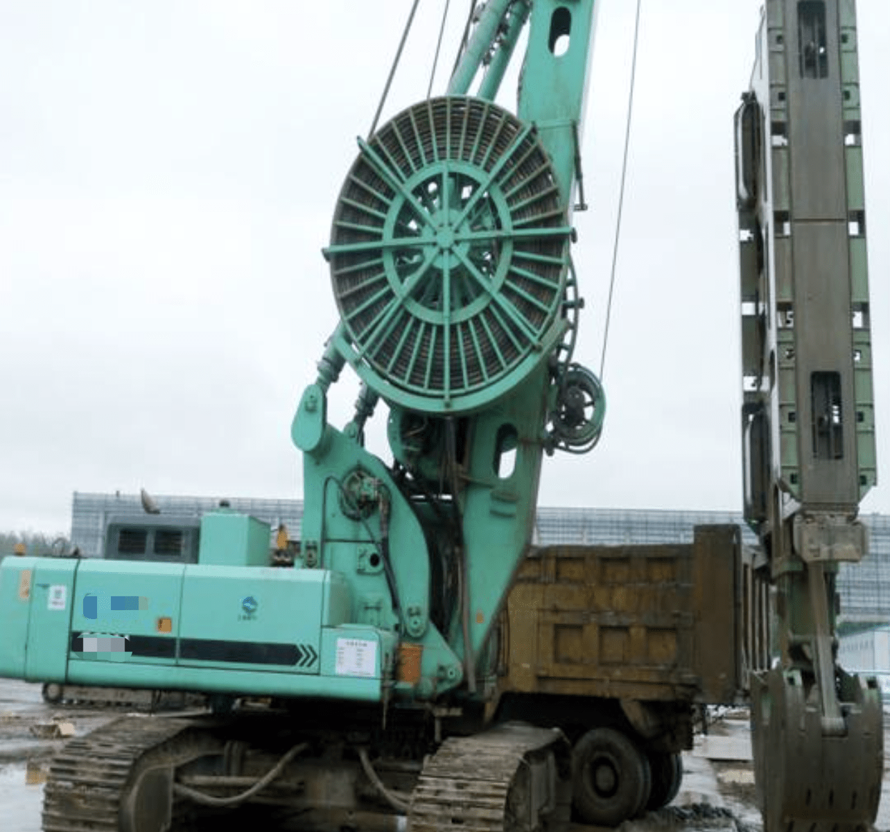
1.3 Trenching
Equipment Types:
-
Grab Machines: Suitable for soils with SPT-N <40 (clay, sand, gravel).
-
Depth: Typically 60–80 m (sufficient for building projects).
-
Efficiency: 8–10 hrs for 35 m walls; ~20 hrs for 60 m walls.
-
-
Impact Machines: Used in hard rock or boulder layers (low efficiency).
-
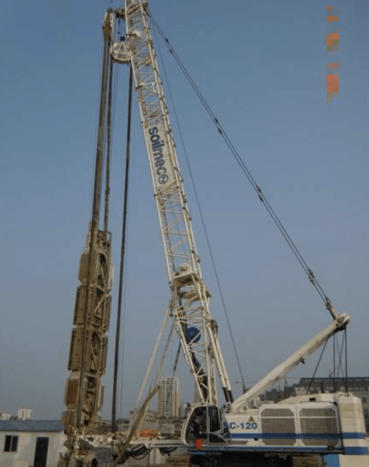
Hydraulic Cutters (Hydrofraise):
-
Advantages: High precision (verticality 1‰–2‰), deep excavation (up to 150 m), and adaptability.
-
Limitations: Expensive, sensitive to obstructions (e.g., rebar, boulders).
-
Trench Division:
-
Segment length: 4–6 m (must exceed grab machine’s horizontal reach of 2.8 m).
-
For SPT-N >50 or rock UCS >3 MPa, use combined grab-impact or grab-cutter methods.
1.4 Joint Systems
Types:
-
Flexible Joints: Pipe joints, hinge joints, cutter joints.
-
Rigid Joints: H-pile joints, cross-steel plate joints, V-plate joints.
Comparison:
| Joint Type | Pros | Cons |
|---|---|---|
| Pipe Joint | Simple, cost-effective | Weak shear resistance, leakage risk |
| H-Pile Joint | High stiffness, good waterproofing | Complex installation |
| Cross-Plate Joint | Excellent seepage control | High steel consumption, expensive |
| Hydrofraise Joint | No pre-excavation needed, high quality | Requires strict sequencing |
1.5 Rebar Cage Construction
Fabrication:
-
Use welding or mechanical couplers (lap joints must stagger by 50%).
-
HRB400 bars (or HRB335 bars ≥25 mm) require mechanical connections.
-
Install lateral supports (2–3 rows) and vertical trusses (4–5 m spacing).
Lifting:
-
Typical weight: 50T (60 m wall); 70T (with H-pile).
-
Use 250–350T main crane + 100T auxiliary crane.
-
Avoid segmented lifting to ensure stability.
1.6 Concrete Pouring
Requirements:
-
Slump: 180–220 mm (underwater concrete).
-
Aggregate size: ≤1/3 of rebar spacing or 1/6–1/8 of pipe diameter.
-
Placement:
-
Dual-pipe method (spacing ≤3 m).
-
Initial embedment depth: ≥0.8 m; maintain 2–6 m during pouring.
-
Quality Checks:
-
Test slump (3+ times per segment) and compressive strength (1 sample/100 m³).
-
Conduct ultrasonic integrity tests (20% sampling) or core drilling.
1.7 Post-Grouting
Specifications:
-
Use P.O.42.5 cement (water-cement ratio: 0.5–0.6).
-
Grout pipes (≥3 per segment) should extend 200–500 mm below wall base.
-
Start grouting after concrete reaches 70% strength.
-
Termination criteria:
-
Grout volume meets design, OR
-
Pressure >2 MPa for 3 mins + 80% design volume.
-
2. Structural Measures for “Integrated Wall” Systems
2.1 Wall Top Lowering
-
Purpose:
-
Accommodate concrete overflow (300–500 mm above design).
-
Avoid conflicts with utility pipes.
-
Merge capping beams with wales to reduce costs.
-
2.2 Settlement Control
-
Solutions:
-
Install edge piles near walls.
-
Use low-rebar or plain concrete in non-load-bearing sections.
-
Enhance connections with structural beams/slabs.
-
2.3 Leakage Prevention
-
Techniques:
-
Rigid joints (e.g., I-shaped) + outer RJP/MJS jet grouting.
-
Internal brick/RC lining with drainage channels.
-
Waterstops at wall-slab joints.
-
3. Safety & Environmental Compliance
3.1 Safety Measures
-
Equipment: Operated by certified personnel.
-
Trench Access: Restricted without proper safeguards.
-
Crane Zones: Marked exclusion areas.
3.2 Environmental Protection
-
Sludge Management:
-
Centralized storage.
-
No direct discharge into waterways.
-
Use sealed trucks for transport.
-
-
Site Monitoring: Pre-construction surveys + real-time building/pipeline checks.
Conclusion
Underground diaphragm walls are a versatile solution for urban deep excavations. Proper construction techniques, joint selection, and waterproofing ensure structural integrity and longevity, especially in “two-wall-in-one” applications. Adherence to safety and environmental protocols further guarantees project success.
