
Classification of Piles
By Load-Bearing Mechanism
Piles are categorized into two main types based on their load transfer mechanism:
-
End-bearing Piles
-
These piles penetrate through weak soil layers to rest on firm strata or bedrock
-
Structural loads are primarily resisted by the rock stratum resistance
-
Construction focuses on controlling embedded rock depth with strict requirements for sediment thickness
-
Most bridge engineering applications require rock embedding
-
-
Friction Piles
-
Entirely installed within weak soil layers
-
Load resistance comes from the combined action of end resistance and side friction between the pile shaft and the surrounding soil
-
Construction emphasizes controlling the design tip elevation (length)
-
Variations include friction-end-bearing piles and end-bearing-friction piles for hard soil layers at the pile tip
-
Bridge engineering applications typically exclude compaction effects
-
By Construction Method
-
Precast Piles
-
Installation methods include:
-
Driven piles
-
Jetted piles
-
Vibratory piles
-
Static pressure piles
-
-
-
Cast-in-place Piles
-
Formed by drilling/boring at the pile location, installing a reinforcement cage, and pouring concrete
-
Classification by boring method:
-
Drilled (percussion) bored piles
-
Manual excavation piles
-
Cased pile construction
-
Blast-expanded piles
-
-
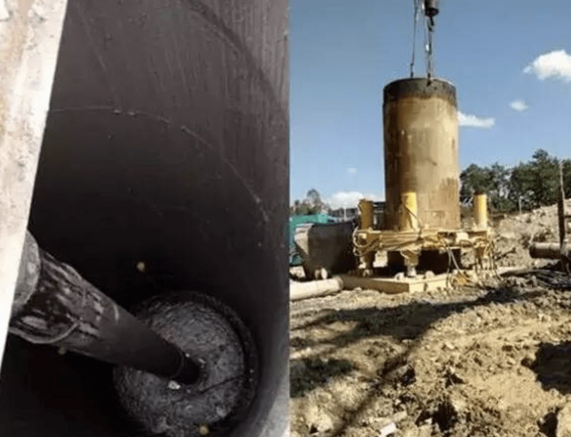
Cast-in-place Concrete Pile Construction
Fundamental Characteristics
Cast-in-place piles are formed by:
-
Creating boreholes mechanically or manually at designated locations
-
Installing reinforcement cages
-
Pouring concrete directly into the excavation
Advantages over precast piles:
-
Adaptability to varying strata
-
Elimination of pile splicing and cutoff requirements
-
Steel savings
-
Reduced vibration and noise
Classification by Excavation Method
-
Dry process drilled piles
-
Slurry-supported bored piles
-
Cased pile construction
-
Manual excavation piles
2.1 Dry Process Drilled Piles
-
Equipment: Typically uses auger drilling rigs with spiral bits (Φ400mm, Φ500mm, Φ600mm diameters for 12m, 10m, 8m depths respectively)
Applicability: Suitable for clay, sandy soil, and artificial fill without groundwater within the drilling depth. Not suitable for water-bearing layers or muddy soil.
-
Positioning: The Rig aligns the drill rod vertically with the pile center. Start drilling slowly, gradually increasing speed to minimize rod wobble, correcting deviations promptly.
-
Base Cleaning: After reaching design depth, remove loose soil to reduce settlement. The method involves idling the drill at the final depth, then lifting to discharge the soil.
-
Reinforcement & Concreting:
-
Ensure main bars, stirrups, diameters, spacing, and cover meet design requirements
-
Use guide bars for cage installation, preventing soil ingress
-
Pour concrete immediately after cage placement to prevent borehole collapse
-
Layered placement (50-60cm layers) with proper compaction
-
2.2 Slurry-supported Bored Piles
-
Principle: Uses circulating slurry to stabilize borehole walls while removing cuttings
Applicability: Effective for both water-bearing and dry soil layers
-
Equipment: Submersible drills, percussion rigs, or grab buckets
-
Construction Sequence:
-
Stakeout
-
Install casing
-
Position rig
-
Prepare slurry
-
Drill (with submersible/percussion rig)
-
Slurry circulation for cuttings removal
-
Clean borehole
-
Install a reinforcement cage
-
Pour underwater concrete
-
2.2.1 Casing Installation & Slurry Preparation
Casing:
-
Install steel casing (4-8mm thick) with 1-2 overflow ports
-
Inner diameter > drill bit diameter by 200mm
-
Functions: Position fixing, orifice protection, water retention, pressure maintenance, and drill guidance
-
Elevation: 1.5m above water table + 0.3m above ground
-
Maintain slurry level ≥1m above external water level
Slurry Properties:
-
Specific gravity: 1.1-1.4 (typically 1.2-1.3, up to 1.4 for unstable strata)
-
Functions:
-
Stabilize the hydrostatic pressure
-
Wall stabilization
-
Cuttings suspension and removal
-
2.2.2 Drilling Methods
-
Rotary (Submersible) Drilling
-
Uses a sealed, waterproof motor and bit assembly
-
Cutting removal methods:
-
Direct circulation: High-pressure slurry injection lifts cuttings via overflow
-
Reverse circulation: Submersible pump directly extracts cuttings
-
-
-
Percussion Drilling
-
Uses weighted chisel bits (cross, I-beam, or V-shaped) dropped freely
-
Initial phase: Low lift (0.4-0.8m) with frequent blows and added rocks for wall support
-
Normal phase: Increase to 1.5-2.0m after casing settles 3-4m
-
Monitor rope condition and alignment regularly
-
-
Grab Bucket Method
-
Utilizes a weighted bucket with movable jaws
-
Suitable for soft soils (sand, clay)
-
Switch to percussion drilling for hard layers
-
2.3 Borehole Inspection
Purposes:
-
Verify position, diameter, depth, and alignment
-
Remove sediment to enhance bearing capacity
Methods:
-
Air lift (0.5MPa pressure) for stable formations
-
Slurry circulation or bucket removal for unstable walls
-
Final slurry SG: 1.15-1.25
-
Sand content: ≤4% (≤2% for large diameters)
Key Points:
-
Clean promptly after reaching depth
-
Use fresh slurry (SG 1.05-1.25) until reinforcement/pipe installation
-
Maintain the water level to prevent collapse
-
Verify average slurry SG meets standards
-
Minimize the time between cleaning and concreting
-
Never compensate cleaning by over-drilling
2.4 Underwater Concrete Placement
Requirements:
-
Concrete grade is one level higher than the design
-
Excellent workability with trial mix
-
Tremie pipe method standard
Procedure:
-
Fill pipe and hopper sufficiently for initial embedment ≥1.0m
-
Cut the suspension plug wire for free flow
-
Maintain 2-6m pipe embedment (avoiding or water pipe blockage)
Critical Parameters:
-
Pipe tip clearance: 20-40cm (optimal sediment removal)
-
Initial volume calculation:
V ≥ πD²/4 × (H1+H2) + πd²/4 × h1
Where:
V = required volume (m³)
D = pile diameter (m)
H1 = tip clearance (0.2-0.4m)
H2 = initial embedment (≥1.0m)
d = pipe inner diameter (m)
h1 = balancing height (h1 = γwHw/γc)
Placement Techniques:
-
Continuous, rhythmic placement with minimal stoppages
-
Slow feed when the pipe isn’t full to prevent airlocks
-
Deeper embedment near reinforcement
-
Final elevation 0.5-1.0m above design for quality assurance
-
Adjust the slurry viscosity if upward flow impedes placement
Leakage Remediation:
-
For localized leaks, use specialized sealing techniques
Pipe Testing:
-
Hydrostatic pressure ≥1.3×water depth pressure
-
Tensile strength ≥1.3P
P = γchc – γwHw
Where:
P = max internal pressure (kPa)
γc = concrete unit weight (24kN/m³)
hc = max concrete column height (m)
γw = slurry unit weight (kN/m³)
Hw = slurry depth (m)
2.5 Quality Requirements & Safety
Quality Control Points
-
Materials: Verify cement, aggregates, and steel compliance
-
Processes: Check the construction sequence and monitoring
2.5.1 Drilling Standards
-
Depth control per design
-
Sediment limits:
-
Friction-dominant: ≤150mm
-
End-bearing-dominant: ≤50mm
-
2.5.2 Reinforcement Cage
-
Uniform main bar distribution
-
Compliance with stirrup spacing, cover requirements
-
Welded connections preferred
-
Installation precautions:
-
±20mm cover tolerance (underwater)
-
±10mm (dry process)
-
Collision prevention during lowering
-
Positive fixation during concreting
-
2.5.3 Concrete Requirements
-
Material quality and batching accuracy
-
Slump control
-
Anti-segregation measures
-
Continuous operation (<4h between cage installation and pouring)
-
Overpour ≥0.5m
-
Minimum volume = calculated quantity
-
Testing frequency:
-
Per shift: ≥1 set
-
Slurry-supported piles: ≥1 set per pile
-
2.5.4 Documentation Requirements
-
Geotechnical reports and drawings
-
Approved construction methodology
-
As-built surveys
-
Construction records
-
Pile integrity reports
-
Load test results
-
Final as-built drawings
2.5.5 Safety Protocols
-
Secure work zones with access control
-
Hazard-specific safety measures
-
Continuous monitoring of:
-
Impact/vibration areas
-
Manual excavation zones
-
Rig stability
-
-
Ground movement awareness
-
Electrical safety measures
Karst Formation Treatment Solutions
Key Challenges
The critical aspect of drilled pile construction in karst regions involves preventing slurry loss and borehole collapse while meeting bearing capacity requirements. Strategic approaches vary based on:
-
Dissolution development degree
-
Cavity dimensions
-
Filling material characteristics
Treatment Methods
3.1 Rock Fragment Backfilling
Procedure:
-
Normal drilling until karst penetration
-
Alternate投放 of clay and rocks (3:7 ratio)
-
Optional additives: cement, soda ash, sawdust (10% of clay)
Materials:
-
Rocks: ≥30MPa granite/limestone (15-50cm)
-
Placement: Layered with clay bags and cement
-
Fill height: 1m above cavity roof
Monitoring:
-
Rig performance
-
Surface settlement
-
Slurry level changes
Precautions:
-
Reduced rope slack (1-2cm) near karst layers
-
Immediate clay/rock addition upon leakage
3.2 Lean Concrete Backfilling
Application: Significant leakage or inclined bedrock
Mix Design:
-
Grade C20 with accelerators
-
Placement to cover inclined surfaces or extend 50cm above the cavity
Curing: 48h minimum (70% strength) before redrilling
3.3 Grouting Reinforcement
Planning:
-
Focus on the largest connected cavities
-
Grout holes serve as supplementary investigation
Parameters:
-
Pressure: 0.5- 1.0MPa (field-tested)
-
Rate: 15-20L/min
-
Radius: ≥3.0m penetration
Materials:
-
Cement slurry (w:c=0.8:1)
-
Mortar option (w:c:s=1:1:0.8)
-
Chemical grout as needed
Execution:
-
Incremental grouting for material economy
-
Sequential hole treatment with pressure escalation
-
Final hole sealing
Conclusion
-
Pile foundations serve as essential deep foundation solutions when shallow foundations prove inadequate for settlement or bearing capacity requirements. Thorough geotechnical investigation forms the basis for proper design and construction.
-
Cast-in-place pile construction involves complex processes including drilling, reinforcement work, cleaning, and concreting. The wet process particularly requires careful quality control due to:
-
Indirect quality verification
-
Process sensitivity to workmanship
-
Potential for latent defects
-
-
Construction methodologies must incorporate:
-
Comprehensive defect prevention strategies
-
Material quality assurance
-
Real-time process monitoring
-
Strict safety protocols
-
-
Karst region construction demands:
-
Pre-construction geological assessment
-
Adaptive treatment selection
-
Contingency planning for unexpected conditions
-
This guide provides a technical framework for ensuring pile foundation quality across various geological conditions while meeting structural performance requirements. Proper implementation of these methods will result in durable, high-capacity deep foundation systems.
