
The function of the pile is to transfer the load of the upper building to the deep soil (rock) layer with a strong bearing capacity or to compact the weak soil layer to improve the bearing capacity and compactness of the foundation soil. In addition to pile foundations, today’s content also explains how to deal with caves.
Classification of Piles
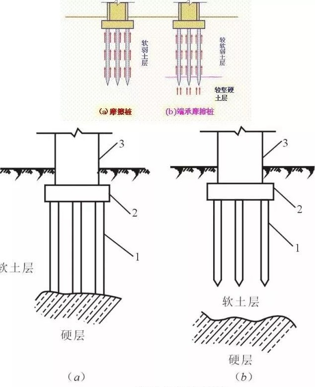
1) Piles are divided into two types according to their stress conditions: end-bearing piles and friction piles.
- End-bearing piles are piles that pass through soft soil layers and reach hard soil layers or rock layers. The structural load is mainly borne by the resistance of the rock layer; during construction, the depth of embedded rock is mainly controlled, and the requirements for sediment thickness are strict.
- ——Most of the end-bearing piles in bridge projects require to be embedded in rock.
- Friction piles are completely installed in the soft soil layer and rely on the resistance of the pile tip and the friction resistance between the side of the pile body and the foundation soil to jointly bear the load. During construction, the design elevation (length) of the pile tip is mainly controlled.
- ——For those with a hard soil layer at the end of the pile, there are also friction end-bearing piles and end-bearing friction piles.
- ——Friction piles in bridge projects usually do not take into account the compaction effect.
2) Piles are divided into prefabricated piles and cast-in-place piles according to construction methods.
According to the method of sinking into the soil, prefabricated piles can be divided into driven piles, water-driven piles, vibration piles, and static pressure piles;
A cast-in-place pile is a pile made by drilling a hole at the pile location, placing a steel frame, and then pouring concrete. According to the different hole-forming methods, cast-in-place piles include drilled (punched) hole cast-in-place piles, dug-hole cast-in-place piles, casing hole-formed cast-in-place piles, and blast-hole cast-in-place piles.
Construction of Cast-in-Place Piles in Mixed Soil
1. Cast-in-place pile: A pile formed by directly drilling holes mechanically or manually at the pile site, placing steel bars in the holes, and pouring concrete.
2. Compared with prefabricated piles, cast-in-place piles are not restricted by changes in the stratum, do not require pile splicing and cutting, save steel, have low vibration, and have low noise.
3. According to the hole forming method, cast-in-place piles are divided into dry-work bored cast-in-place piles, mud-wall-formed cast-in-place piles, immersed tube cast-in-place piles, artificially dug cast-in-place piles, etc.
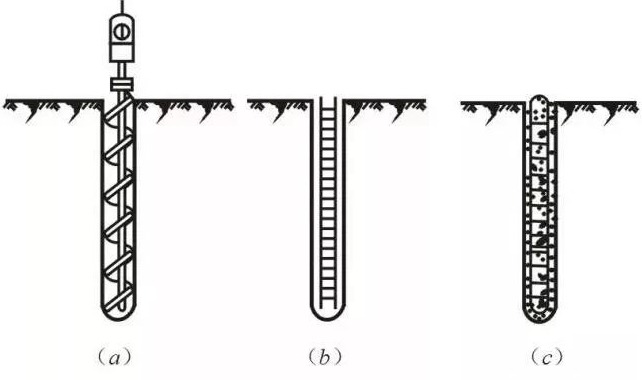
2.1 Dry operation bored piles
1. Holes for dry operations are generally drilled using auger drills. The outer diameters of the spiral drill bits are Φ400mm, Φ500mm, and Φ600mm respectively, and the drilling depths are 12m, 10m, and 8m respectively. It is suitable for general clay layers, sandy soils, and artificial fill foundations without groundwater within the hole formation depth, and is not suitable for soil layers and silty soils with groundwater.
2. After the drilling rig is in place, align the drill pipe vertically with the center of the pile. When drilling, start slowly and then quickly to reduce the shaking of the drill pipe and correct the deflection or displacement of the borehole promptly.
3. After drilling the hole to the required depth, clean the soil at the bottom of the hole. The purpose of hole cleaning is to remove the floating soil and virtual soil in the hole to reduce the settlement of the pile. The method is to idle the drill at the original depth to clear the soil, then stop rotating and lift the drill to unload the soil.
4. The main bars, stirrups, diameter, number, spacing, and protective layer of the main bars of the steel frame should comply with the design requirements, and be tied firmly to prevent deformation. Use guide steel bars to feed them into the holes while preventing soil and debris from falling into the holes. After the steel frame is in place, concrete should be poured immediately to prevent holes from collapsing. When pouring, it should be poured and compacted in layers, with the thickness of each layer being 50 to 60cm.
2.2 Mud wall retaining hole cast-in-place pile
1. Mud wall protection hole forming is a mechanical drilling method that uses mud to protect and stabilize the hole wall. It uses circulating mud to suspend the chopped debris and then discharge it out of the hole. It is suitable for soil layers with and without groundwater.
2. Hole-forming machinery includes diving drills, impact drills, punching cones, etc.
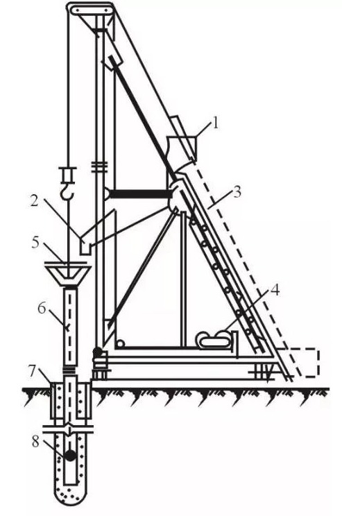
3. The construction process of cast-in-place cast-in-place piles with mud retaining walls: determining the pile position, burying the casing, placing the pile driver, preparing mud, drilling the hole mechanically (submersible drilling rig, impact drilling rig, etc.), circulating mud to remove slag, cleaning the hole, and placing it. Reinforced steel frame, pouring underwater concrete.
2.2.1 Embedding the casing and preparing mud
① Before drilling, lay out the line and position it on site, dig out the topsoil of the pile hole according to the pile position, and bury the casing. There are 1 to 2 overflow holes on the upper part of the casing. It is a cylinder made of steel plates with a thickness of 4 to 8 mm. Its inner diameter should be 200 mm larger than the diameter of the drill bit. The function of the casing is to fix the position of the pile hole, protect the hole opening, prevent groundwater from flowing in, increase the water pressure in the hole, prevent the hole from collapsing, and guide the direction of the drill bit when the hole is formed.
The top of the casing is 1.5m higher than the construction water level and 0.3m higher than the ground.
② Ensure that the top elevation of the mud inside the casing is always at least 1m higher than the external water level.
During the drilling process, mud with a relative density of 1.1 to 1.4 is injected into the hole. Generally 1.2~1.3; for prone-to-collapse strata, it can be increased to about 1.4.
③ Function of mud:
Stable water pressure:
Make the pores in the soil layer in the hole wall of the pile hole seep and fill tightly to avoid water leakage in the hole and keep the water pressure in the casing stable;
Protective wall:
The relatively high density of mud increases the water pressure in the hole, which can stabilize the hole wall and prevent hole collapse;
Floating (carrying) slag:
By circulating mud, the cut debris can be suspended and discharged, playing the role of carrying sand and discharging soil.
2.2.2 Hole Formation
1) Swing (diving) drilling rig into holes
The rotary drilling rig is a rotary drilling machine. Its waterproof motor speed change mechanism and drill bit are sealed together. After being positioned by the pile frame and drill rod, it can dive into water and mud to drill holes. After the mud is injected, the cut soil particles and gravel in the hole are discharged out of the hole through the forward circulation or reverse circulation slag removal method.
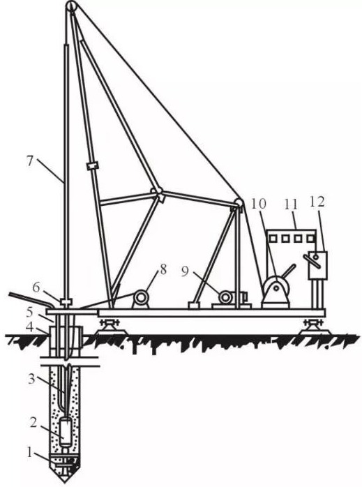
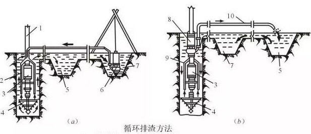
There are two methods of slag discharge for hole forming in rotary drilling rigs: forward circulation slag discharge and reverse circulation (pump lift) slag discharge.
① Positive circulation slag removal method
During the drilling process, the rotating drill bit cuts the crushed mud into a slurry, and then uses a mud pump to send high-pressure mud through the center tube and branch pipes of the drilling rig to the bottom of the drill bit and sprays it out forcefully, and mixes with the slurry cut into a slurry. The crushed mud and slag are mixed, carrying the soil upward along the hole wall, and discharged from the overflow hole of the casing.
② Reverse circulation slag removal method
The sand and gravel pump dives into the hole together with the main engine and directly pumps the cutting debris out of the hole along with the mud.
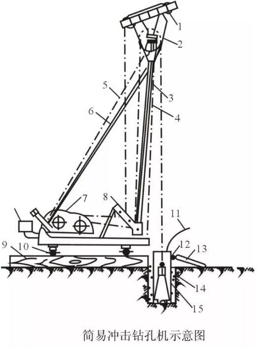
2) Impact drilling into holes
The impact drill raises the heavy drill bit (impact hammer) with a blade to a certain height through the frame and winch and relies on the impact force of free fall to cut and break the rock layer or impact the soil layer to form holes.
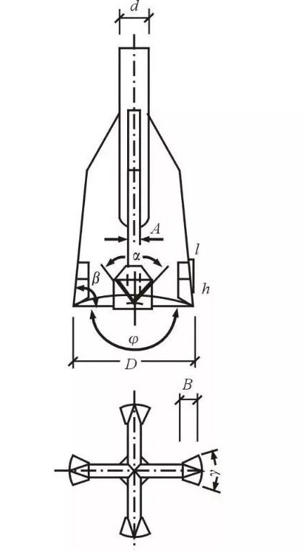
② Impact drill bits are available in cross-shaped, I-shaped, herringbone, etc. Generally, cross-shaped impact drill bits are commonly used.
③ Before punching, the steel casing should be buried and the wall protection material should be prepared.
After the impact drill is in place, align the center of the ram with the center of the casing. The density punch should be lowered within the range of 0.4 to 0.8m in the stroke, and rocks and mud should be added in time until the casing sinks 3 to 4m, and the stroke can be Raised to 1.5~2.0m, switch to normal impact, and measure and control the relative density of mud at any time.
During construction, the damage to the wire rope, the tightness of the jammed machine, and the flexibility of the steering device should be frequently checked to avoid dropping the drill.
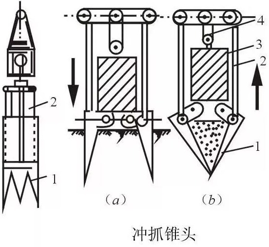
3) Punch the cone into the hole
① There is a heavy iron block and a movable grabbing piece on the cone head of the punching and grabbing cone. The punching and grabbing cone is raised to a certain height through the frame and hoist. When it falls, the drum brake is released, the grabbing piece opens, and the cone head falls freely and rushes. into the soil, and then start the winch to lift the cone head, and then the grabbing piece is closed to grab the soil. The punching and grabbing cone is lifted to the ground as a whole to remove the soil residue, which is then circulated to form holes.
② The construction process, casing installation requirements, mud retaining wall circulation, etc. of the impact cone drilling construction are the same as those of the impact drilling construction.
③ It is suitable for punching holes in soft soil layers (sand, clay), but when encountering hard soil layers, it is better to use an impact drill instead.
2.3 Hole inspection
1. Hole inspection is to use detectors to check the pile position, diameter, depth, and tunnel conditions; hole cleaning is to remove sediment and silt floating soil at the bottom of the hole to reduce the settlement of the pile foundation and improve the bearing capacity.
2. When clearing holes in the mud wall protection wall, for pile holes with good soil quality that are not easy to collapse, you can use an air suction machine to clear the holes. The air pressure is 0.5MPa, so a strong high-pressure airflow is formed in the pipe and rises upward. At the same time, the clean water is continuously replenished and stirred. The sludge rises with the airflow and is discharged from the nozzle until clean water is sprayed out.
3. For hole walls with poor stability, the mud circulation method should be used to clean the holes or pump cylinders to discharge slag. The relative density of the mud after hole cleaning should be controlled at 1.15~1.25. Sand content <=4% (2% for large diameter piles)
Hole cleaning operation:
1. After the drilling reaches the required depth, use a mud pump to clean the hole on time to avoid too long a delay and the precipitation of mud drilling residue, which may cause difficulty in hole cleaning or hole collapse.
2. After the final hole is drilled to the designed depth, lower the slurry pipe to 50 to 80cm from the bottom of the hole. Use fresh mud with a specific gravity of 1.05 to 1.25 to clean the hole until the steel bars and conduits are lowered into the hole and then measure the sediment at the bottom of the hole again. thickness. The next step of construction can only be carried out until the thickness of the sediment meets the requirements.
3. Pay attention to maintaining the water head in the hole to prevent hole collapse;
4. After cleaning the hole, check the average specific gravity of the mud extracted from the hole mouth, the hole middle, and the hole bottom, and it should meet the quality standard requirements.
5. Take all measures to shorten the time from cleaning the hole to pouring underwater concrete.
6. Do not use deepening the hole instead of clearing the hole.
2.4 Pouring underwater mixed soil
The pouring of mud wall retaining hole-forming concrete is carried out in water or mud, so it is called pouring underwater concrete.
Underwater concrete should be one strength level higher than the design strength, must have good workability, and the mix ratio should be determined through testing.
The conduit method is commonly used for underwater concrete pouring.
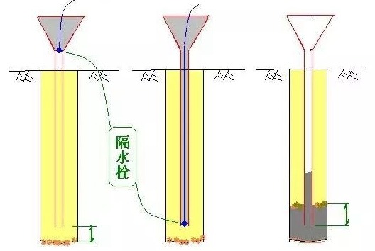
When pouring, first fill the conduit and the funnel with concrete to an amount that ensures that the lower end of the conduit is buried more than 1.0m below the concrete surface at one time, and then cut (or quickly pull out) the steel wire that suspends the water isolating bolt. The concrete mixture will act under its weight. Quickly drain the ball plug into the water.
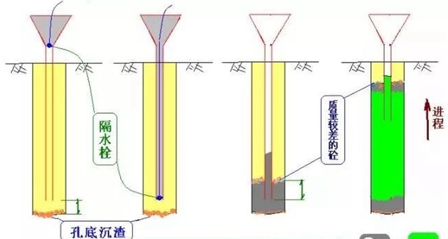
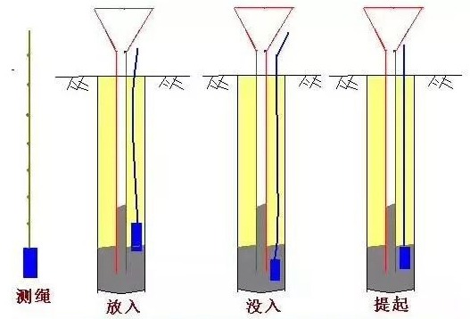
The buried depth of the conduit should be kept between 2 and 6m
——If it is too small, water may enter the conduit; if it is too large, it may lead to “buried pipes”.
1. The distance from the conduit mouth to the bottom of the hole should not be too large or too small, generally 20 to 40cm. If it is too large, it is not conducive to lifting the sediment, and the quality of the bottom concrete is difficult to guarantee; if it is too small, it will easily block the pipe.
2. To prevent water from entering the conduit, the first plate of concrete should be buried so that the conduit is not less than 1m deep.
Before pouring, detect the mud sedimentation thickness at the bottom of the hole. If it is greater than the designed thickness, clean the hole again until the requirements are met.
The concrete is produced by the mixing station and transported to the site by bucket truck for inspection of workability, slump, and other indicators. If the requirements are not met, secondary mixing should be performed. If the secondary mixing still does not meet the requirements, it must not be used, and then weigh and cut materials according to the mix ratio again until the requirements are met.
When pouring the first batch of concrete, you should pay attention to:
a. The distance from the lower opening of the catheter to the bottom of the hole is generally 20 to 40cm.
b. The first batch of concrete reserves should ensure that the conduit is buried ≥1.0m into the concrete surface at a time;
The required mixing quantity is calculated according to the formula:
V≥∏D²/4· (H1+H2)+ (Πd²/4)h1
V—the quantity required for pouring the first batch of concrete (m³);
D—pile hole diameter (m);
H1—the distance from the bottom of the pile hole to the bottom of the conduit, generally 0.2 to 0.4m;
H2—the initial embedding depth of the catheter (m);
d—catheter inner diameter (m);
h1—When the concrete in the pile hole reaches the embedding depth H2, the height (m) required for the concrete column in the conduit to balance the pressure outside the conduit (or mud), that is
h1 = rwHw/rc;
A dedicated person will measure the buried depth of the pipe and the height difference between the inner and outer concrete surfaces of the pipe, and fill in the concrete pouring record.
After the back-sealing concrete is poured, the back-sealing condition should be carefully checked. After confirming that the back sealing is successful, proceed with normal pouring.
When pouring begins, it should be carried out continuously and rhythmically, and the time for removing the conduit should be shortened as much as possible;
When the concrete in the conduit is not full, pour it slowly to prevent high-pressure airbags from forming in the conduit and causing leakage of the conduit.
When the concrete surface of the good hole is close to the steel frame, keep the conduit at a slightly larger burial depth and slow down the pouring speed; when the concrete surface of the good hole enters the steel frame to a certain depth, lift the conduit appropriately so that the steel frame has a certain depth in the concrete. Burial depth, stabilize the steel bars, and pay attention to control the center position of the steel cage.
To ensure the quality of the pile top, the concrete pouring is 0.5 (0.6) ~ 1.0m higher than the design elevation of the pile top.
Near the end of pouring, the height of the concrete column in the conduit is relatively reduced, and the concrete pressure in the conduit decreases, while the consistency and specific gravity of the mud in the well hole outside the conduit increases. If it is difficult to lift the concrete, add water to the hole to dilute the mud and remove some of the precipitated soil to make the pouring work go smoothly.
If water leakage is found in the pipe and the location of the accident can be determined, this method can be used to remedy it. The requirements for craftsmanship and experience are relatively high.
Conduit watertight pressure bearing and joint tensile test:
During the watertight pressure-bearing test of the conduit and the tensile test of the joint, the water pressure in the pipe should not be less than 1.3 times the water depth in the hole, nor should it be less than 1.3P of the maximum internal pressure that the conduit wall and weld can withstand when pouring concrete.
P is calculated according to the following formula:
P=rchc-rwHw
p—the maximum internal pressure that the catheter may bear (Kpa);
rc—the specific gravity of the concrete mixture (taken as 24KN/m³);
hc—maximum height of concrete piles in the conduit (m), based on the full length of the conduit or the expected maximum height;
RW—bulk density of water or mud in the wellbore (KN/m³);
Hw—The depth of water or mud in the wellbore (m).
2.5 Quality requirements and complete technology for cast-in-place pile construction
The quality inspection of cast-in-place pile construction includes quality inspection of three construction processes: hole forming and hole clearing, steel frame production and placement, and concrete mixing and pouring.
Raw materials such as cement, sand, gravel, and steel should be inspected before construction, and the construction sequence and monitoring methods formulated in the construction organization design should also be inspected.
2.5.1 Hole forming quality inspection and requirements
1. Control requirements for the depth of cast-in-place pile holes:
Holes formed by mud retaining walls and holes formed by dry operations should reach the depth specified in the design.
2. The sediment thickness of the cast-in-place pile:
When the friction force is the main factor, it shall not be larger than 150mm; when the end bearing force is the main factor, it shall not be larger than 50mm.
2.5.2 Requirements for the production and placement of steel cages
When making the steel cage, the main bars are required to be evenly arranged in the circumferential direction. The diameter and spacing of the stirrups, the protective layer of the main bars, and the spacing of the stiffening hoops should all meet the design requirements. Welding should be used between main bars and stirrups. Stiffening hoops should be set outside the main bars. The main bars generally do not have hooks. According to the requirements of the construction technology, the hooks must not be exposed to the inner ring to avoid hindering the construction.
The allowable deviation of the protective layer of the main bars of the steel cage is ±20mm for underwater concrete piles; and ±10mm for non-underwater concrete piles.
During the production, transportation, and installation of steel cages, measures should be taken to prevent deformation, and protective layer pads (or pad tube, pads) should be provided. When hoisting into the hole, avoid hitting the hole wall. When pouring concrete, measures should be taken to fix the position of the steel cage.
2.5.3 Concrete mixing and pouring
1. Concrete mixing mainly checks the material quality and proportion measurement and concrete slump; when pouring concrete, measures to prevent concrete segregation, pouring thickness, and vibration compaction should be checked.
2. Each process of cast-in-place piles should be constructed continuously. After the mud is placed in the steel cage, concrete must be poured within 4 hours.
3. After pouring, the top of the pile should be 0.50m higher than the design elevation. The actual amount of concrete poured for cast-in-place piles shall not be less than the calculated volume.
4. When pouring concrete, there should be no less than one group of test blocks with the same proportion per shift; there should be no less than one group of cast-in-place piles with holes in the mud wall protection wall.
5. The quality inspection standards for concrete cast-in-place piles should comply with regulations.
2.5.4 Construction Acceptance Data
The acceptance of pile foundation construction should include the following information:
(1) Engineering geological survey report, pile foundation construction drawings, drawing review minutes, design change orders material substitution notices, etc.
(2) Changes in the approved construction organization design, construction plan, and execution.
(3) Pile position measurement and setting out drawing, including project pile position line review visa form.
(4) Hidden construction records of pile holes, steel bars, and concrete projects, as well as quality inspection and acceptance sheets and construction records of each sub-project.
(5) Pile quality inspection report.
(6) Single pile bearing capacity test report.
(7) The completed pile position plan and pile top elevation plan after the foundation pit is dug to the design elevation.
2.5.5 Pile Foundation Engineering Safety Technology
(1) Closed management should be implemented in the pile foundation project construction area. All types of construction personnel entering the site must receive safety education, strictly follow the operating procedures, obey instructions, stick to their posts, and concentrate on operations.
(2) According to the construction characteristics of different types of piles and unsafe factors, reliable safety measures should be formulated and implemented strictly.
(3) Inspection and inspection of hazardous areas and machinery (impact and hammer pile drivers, around manually excavated holes, and under pile frames) should be strengthened. If there is any danger or abnormal situation, construction should be stopped immediately and reported promptly. Construction can only continue after the relevant personnel has identified the cause, eliminated the danger, or reinforced it.
(4) During the piling process, the soil on the stopping surface may be squeezed, bulged, or subsided. The piling machinery and pile frame should be adjusted at any time to maintain stability and prevent accidents.
(5) Strengthen the maintenance and management of mechanical equipment, and electromechanical equipment should have anti-leakage devices.
Cave Treatment Plan
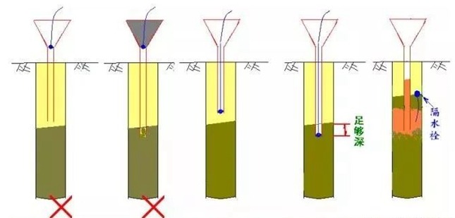
The key to the construction of bored piles in karst areas is how to ensure that there is no leakage of slurry during the hole formation process, or that the hole does not collapse despite leakage of slurry, to ensure that the pile holes are smoothly formed, the piles are formed, and the bearing capacity requirements are met. During construction, the situation of karst strata should be identified according to the geological borehole histogram provided by the design, so that you can be aware of it and take precautions in advance. Therefore, according to the development status of the corrosion, the size of the cavity, and the filling conditions of the cave, the pile foundation construction adopts the conventional mud wall protection method, throwing rubble into the hole, backfilling with lean concrete, pressure grouting, and following up with steel casing.
3.1 Backfilling with rubble
The normal hole-forming method is used for construction. When the karst cave is drilled and the slurry leaks out, loess and rubble are repeatedly put in, and the loess and rubble are squeezed into the cave and karst fissures by using the drill bit. Cement, caustic soda, and sawdust can also be added to enlarge the hole. The self-stabilizing ability of the wall.
1. Adding ratio To effectively utilize the flakes, the ratio of flakes to clay is 3:7, and the mixing ratio is 2 bags per meter. When adding sawdust, the mixing ratio is 10% of the clay.
2. Adding method: Granite or limestone with a strength of ≥30Mpa is used as the flake stone, and the particle size of the stone is preferably 15-50cm.
When adding clay, the effect will be better if it is packaged in cement bags. The best way to put cement is to put it in the whole bag.
The mixing method is: gravel, clay bags, and cement or sawdust (if added) are added at intervals in layers, and the backfill height is 1m above the roof of the cave.
3. Construction precautions: Pay close attention to the working conditions of the drilling rig, surrounding surface settlement, and water level changes in the casing to prevent abnormal situations and slurry leakage from occurring, and handle them immediately.
According to the geological column chart, observe and check frequently when approaching a karst cave. Use the feel of the main impact rope in your hand, the sound of the drill bit hitting the rock formation, and the extracted rock samples to determine whether it is close to the karst formation.
When approaching the karst, the amount of slack in the main rope should be 1-2cm to prevent the drill from getting stuck when penetrating the rock shell.
Once slurry leaks when drilling through the upper crust of karst strata, clay blocks, and gravel should be put in the time and water should be replenished to maintain the water level in the hole.
3.2 Lean concrete backfill
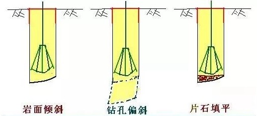
The normal hole-forming method is used for construction. When drilling through the cave and leaking slurry or encountering an inclined rock surface, low-grade concrete is filled in. After a certain period, a percussion drill is used to create the hole.
1. Concrete grade and mix ratio Concrete grade usually uses C20 lean concrete. To increase the strength of concrete as soon as possible and save construction time, a certain early strength agent should be added to the concrete to improve the early strength of lean concrete.
2. Adding method: For inclined rock surfaces, to correct the hole position, the backfilled lean concrete should be flush with the top surface of the inclined rock surface. For karst caves, the top surface of the backfill should be 50cm higher than the roof of the cave.
3. Construction precautions: After backfilling for 48 hours, the strength of the backfill concrete reaches 70% before drilling can be resumed.
3.3 Grouting reinforcement
The grouting method to treat bored pile caves is a method of filling and reinforcing the caves that the bored piles pass through based on the geological survey data provided by the design institute. This method is a very effective measure for treating large caves.
1. Layout of grouting holes. According to the design information provided by the design institute, first find the largest cave. If the cave is connected, only the largest cave needs to be reinforced by grouting. In addition, drilling grouting holes is also based on the geological conditions. Further exploration will be carried out to determine the height of the cave and the details of the filling through core taking.
2. Grouting pressure control: Use a grouting pump for grouting. The grouting pressure should not be too high and should be controlled within the range of 0.5-1.0MPa. The specific pressure value is determined by on-site testing. The grouting speed is 15-20L/min. The purpose is to allow the slurry to penetrate the filling (including poured sand or gravel) and then consolidate. The minimum penetration diameter is set to 3.0m to ensure that the hole is punched and drilled. There is sufficient consolidation. During grouting, the grouting pipe must be inserted into the bottom of the filler, and then slowly lifted while grouting. The pipe lifting speed should not be too fast. The penetration radius should be controlled within the allowable range based on the grouting speed. The slurry is cement slurry, using grade 32.5 cement. The cement mix ratio is water:cement=0.8:1.0. If cement mortar is required, the mix ratio should be water:cement:sand=1:1:0.8. When double-liquid slurry is required, the amount of water glass should be determined based on field tests.
3. Precautions for grouting construction: To prevent the slurry from losing too far and causing waste, the intermittent grouting method is adopted, so that the slurry is injected first the sand (or gravel) is initially cemented before grouting, and the grouting is cycled multiple times until it reaches Until the minimum grouting volume and grouting pressure control value are specified. After grouting one hole, continue grouting the remaining holes. The pressure of the final grouting must be increased, and the hole must be sealed finally. The grouting sequence is controlled by the site.
summary
1) Pile foundation is a commonly used form of deep foundation. When the settlement of the shallow foundation on the natural foundation is too large or the bearing capacity of the foundation cannot meet the design requirements, a pile foundation should be used. Engineering geological survey is an important basis for pile foundation design and construction.
2) The construction of cast-in-place piles includes construction processes such as hole formation, steel cage production and installation, hole cleaning, and concrete pouring. The pile formation process is complicated. The pile formation speed is slow when drilling holes in wet work. The quality of the pile formation is closely related to the quality of the construction. Relatedly, the pile quality is difficult to visually inspect. In the cast-in-place pile construction plan, quality accidents must be carefully analyzed and corresponding preventive measures must be taken.
Thank you!
