
As a foundation pit enclosure structure, the underground diaphragm wall is designed and calculated mainly based on three major aspects: strength, deformation, and stability. Strength mainly refers to the horizontal and vertical section bearing capacity of the wall and the vertical foundation bearing capacity; deformation Mainly refers to the horizontal deformation of the wall and the vertical deformation of the vertical load-bearing structure; stability mainly refers to the overall stability of the foundation pit enclosure structure, anti-overturning stability, anti-uplift stability of the pit bottom, anti-seepage stability, etc., stability calculation method. The main aspects of underground diaphragm wall design are detailed below.
1. Wall thickness and slot width
The thickness of underground diaphragm walls is generally 0.5 to 1.2m. With the enlargement of trenching equipment and the improvement of construction technology, the thickness of underground diaphragm walls can reach more than 2.0m. The thickness of the cylindrical underground continuous wall of the Shin-Toyosu underground substation in Tokyo Bay, Japan reaches 2.40m. The excavation depth of the foundation pit of the Shanghai World Expo 500kV underground substation is 34m, and the enclosure structure adopts a 130m diameter cylindrical underground diaphragm wall with a thickness of 1.2m and a wall depth of 57.5m. In a specific project, the thickness of the underground diaphragm wall should be comprehensively determined based on the specifications of the troughing machine, the anti-seepage requirements of the wall, and the stress and deformation calculation of the wall. Common wall thicknesses for continuous underground walls are 0.6, 0.8, 1.0, and 1.2m.
When determining the planar shape and groove width of underground diaphragm wall unit trough segments, many factors need to be considered, such as the structural stress characteristics of the wall segments, the stability of the trough wall, the protection requirements of the surrounding environment, and construction conditions, etc. All factors need to be combined. Determined comprehensively. Generally speaking, the width of wall plate-type straight trough sections should not be greater than 6m, and the total width of each limb of T-shaped, folded line trough sections and other trough sections should not be greater than 6m.
2. The penetration depth of underground continuous walls
In general projects, the depth of underground continuous walls in the soil ranges from 10 to 50m, and the maximum depth can reach 150m. In the foundation pit project, the underground diaphragm wall not only serves as a stress-bearing structure to withstand lateral water and soil pressure but also has the function of water isolation. Therefore, the depth of the underground diaphragm wall needs to consider both soil retaining and water isolation requirements. As a retaining structure, the depth of the underground diaphragm wall must meet various stability and strength requirements. As a water-isolating curtain, the depth of the underground diaphragm wall must be determined based on groundwater control requirements.
1. Determine the depth of penetration based on stability
As a stress-retaining enclosure, the bottom of the underground diaphragm wall needs to be inserted to a sufficient depth below the base and into a good soil layer to meet the embedding depth and various stability requirements of the foundation pit. In soft soil strata, the embedding depth of underground diaphragm walls below the base is generally close to or greater than the excavation depth to meet stability requirements. When there is a soil (rock) layer with good physical and mechanical properties such as a dense sand layer or rock layer below the base, the embedding depth of the underground diaphragm wall below the base can be greatly shortened. For example, the excavation depth of the Shanghai Rail Transit Line 7 Yaohua Road Station Comprehensive Development Project is about 20.4m. The soft plastic clay layer below the base is mainly used. An underground continuous wall is used as the enclosure structure. The wall must be embedded 19m below the base to meet the requirements. stability requirements. The excavation depth of the Nanjing Greenland Zifeng Building is about 21.4m, and everything below the base is weathered andesite. The underground diaphragm wall is embedded 7m below the base to meet the stability requirements.
2. Consider the water isolation effect to determine the depth of penetration
As a water-isolating curtain, the underground diaphragm wall needs to be designed based on the hydrogeological conditions below the base and groundwater control to determine the depth of penetration. When groundwater needs to be cut off or groundwater bypass paths need to be increased according to groundwater control requirements, the bottom of the underground diaphragm wall needs to enter the water-insulating layer. Cut off the hydraulic connection between the diving and pressurized water inside and outside the pit, or insert it deep enough below the base to ensure the formation of a reliable water barrier. If the depth of the underground diaphragm wall determined according to the water isolation requirements is greater than the depth determined by the stress and stability requirements, to reduce economic investment, the deeper part of the underground diaphragm wall to meet the water isolation requirements can be poured with plain concrete.
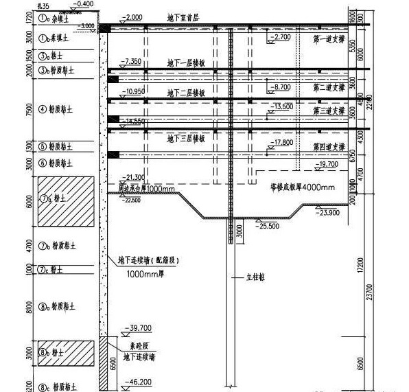
The excavation depth of the Tianjin Jinta foundation pit is 22.1m, and a 1.0m-thick “two walls in one” underground continuous wall is used as the enclosure. There is a second confined aquifer (8b) in the silt layer about 40m deep below the ground. The foundation pit does not meet the requirements for the stability of confined water surges, and isolation measures need to be taken according to the environmental protection requirements around the base. According to the stability calculation, the underground diaphragm wall inserted 17.2m below the base can meet various stability requirements. To isolate the second pressurized water, the bottom of the underground diaphragm wall needs to enter the (8c) silty clay layer, and the depth below the base needs to reach 23.7m. Therefore, considering the factors of stability and isolation of pressurized water, the underground diaphragm wall is inserted 23.7m below the base. According to the stress and stability requirements, reinforced concrete is used in the range of 17.2m below the base, and the section 17.2~23.7m below the base. Plain concrete sections are used as water-proof curtains. The project has been completed, and the plain concrete section of the lower part of the underground diaphragm wall has effectively blocked the secondary pressurized water.
3, Internal Force and Deformation Calculation and Bearing Capacity Verification
1. Internal force and deformation calculation
The planar elastic foundation beam method is currently the most widely used method for calculating the internal forces and deformations of underground diaphragm walls as foundation pit enclosure structures. This method is simple to calculate and can be applied to most conventional projects; for deep foundation pit projects with obvious spatial effects, the spatial elastic foundation plate method can be used to calculate the internal forces and deformations of underground diaphragm walls; for complex foundation pit projects, the continuum finite element method needs to be used for calculations.
The calculation of wall force and deformation should be based on the beam and plate layout of the underground structure of the main project, as well as construction conditions and other factors, and the calculation conditions such as support elevation and layered excavation depth of the foundation pit should be reasonably determined, and the calculation mode should be selected based on the actual conditions inside and outside the foundation pit. , taking into account the layered excavation of the foundation pit and the layered setting of supports, as well as the time sequence and spatial location of working conditions such as support replacement and removal, and continuous and complete design calculations under various working conditions.
2. Bearing capacity verification
The cross-sectional bearing capacity check and reinforcement calculation of underground continuous walls should be carried out based on the internal force calculation envelope diagram of each working condition. Conventional wall panel-type underground diaphragm walls need to be checked for normal section bending and oblique section shear bearing capacity. When they need to bear vertical loads, vertical compression bearing capacity needs to be checked. For cylindrical underground diaphragm walls, in addition to the normal section bending, oblique section shear, and vertical compression bearing capacity verification, the circumferential compression bearing capacity also needs to be verified.
When the underground diaphragm wall is only used as the foundation pit enclosure structure, the reinforcement calculation for the underground diaphragm wall should be based on the limited state of bearing capacity. When the underground diaphragm wall also serves as the main structure during the normal use stage, the reinforcement calculation should be based on the limit state of normal use. Crack control requires reinforcement calculations.
The design and calculation of the bending, compression, and shear bearing capacity of the normal section of the underground diaphragm wall and the reinforcement design should comply with the relevant provisions of the current national standard “Code for Design of Concrete Structures” (GB50010).
4. Design and Structure of Underground Continuous Wall
1. Wall Concrete
The design strength grade of concrete for underground diaphragm walls should not be lower than C30. During underwater pouring, the concrete strength grade should be increased according to relevant specifications. The joints between the wall and the trough section should meet the anti-seepage design requirements, and the concrete anti-seepage grade of the underground diaphragm wall should not be less than S6. The protective layer of the main reinforcement of the underground diaphragm wall should not be less than 50mm on the inside of the foundation pit, and should not be less than 70mm on the outside of the foundation pit.
The concrete pouring surface of the underground diaphragm wall should be 300 to 500mm higher than the design elevation. The wall top elevation and wall concrete strength after removing the laitance layer should meet the design requirements.
2. Steel cage
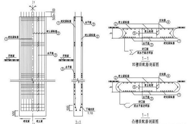
The underground diaphragm wall steel cage is composed of longitudinal steel bars, horizontal steel bars, sealing steel bars, and structural reinforcement steel bars. The longitudinal steel bars are evenly arranged along the wall and can be arranged in sections along the depth of the wall according to the force. Longitudinal steel bars should be HRB335 or HRB400 steel bars. The diameter should not be less than 16mm, and the clear spacing of the steel bars should not be less than 75mm. When the amount of longitudinal steel bars in the underground diaphragm wall is large and the steel bar layout cannot meet the clear spacing requirements, in actual projects, the longitudinal steel bars are often used. Adjust the net spacing of the steel bars by merging and binding two adjacent steel bars to ensure dense concrete pouring. Longitudinal steel bars should minimize steel bar joints and should be configured with more than half full length. Horizontal steel bars can be HPB235 grade steel bars, and the diameter should not be less than 12mm. The diameter of the sealing steel bars should be the same as the horizontal steel bars, and the vertical spacing should be the same as the horizontal steel bars or set according to the horizontal steel bar spacing. The underground diaphragm wall should be equipped with structural reinforcing steel bars such as erecting trusses according to the overall stability and deformation requirements of the steel cage during the hoisting process.
There should be a gap of no more than 150mm between the ends of both sides of the steel cage and the joint pipe (box) or the concrete joint surface of the adjacent wall section. The lower end of the steel bar within the length of 500mm should be closed in a ratio of 1:10, and the steel cage should be closed There should be a gap of not less than 500mm between the lower end of the groove and the bottom of the groove. The shape of the steel bars at the underground diaphragm wall steel cage head should match the construction joints. Sealing steel bars and horizontal steel bars should be welded with equal strength.
The steel cage of the unit tank section should be assembled as a whole on the processing platform and sunk into the tank as a whole at one time. When the steel cages in the unit tank section must be assembled and deposited in sections, mechanical connections should be used to connect the upper and lower steel cages, and pre-assembly measures should be taken on the ground to facilitate the quick connection of the upper and lower steel cages. The location of the joints should be selected in the area under the load. where the force is smaller and staggered from each other.
(1) Corner trough section steel cage
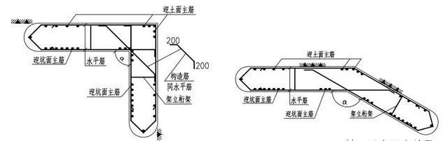
The horizontal bars on the side of the corner trough section with an angle smaller than 180 degrees should be anchored into the opposite wall to meet the anchoring length and should be welded to the opposite side horizontal steel bars to enhance the overall stiffness of the corner trough section during the hoisting process. Diagonal structural steel bars should be installed at the corners to enhance the overall stiffness during the hoisting process of the corner trough section.
(2) T-groove section steel cage
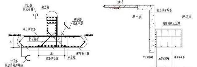
The extended web of the T-shaped trough section should be set on the side facing the soil to prevent it from affecting the construction of the main structure. According to the relevant specifications, the T-shaped groove section section design and reinforcement calculation are carried out. The steel bars in the side tension area of the wing plate can be evenly arranged within one time of the wall thickness on both sides of the web.
3. Wall crown beam
A closed reinforced concrete crown beam should be set at the top of the underground diaphragm wall. The height and width of the crown beam are determined by calculation, and the width should not be less than the thickness of the underground diaphragm wall. The underground diaphragm wall is constructed in sections, and a full-length top ring beam is installed on the top of the wall to enhance the integrity of the underground diaphragm wall. The top ring beam should be flush with the soil-facing surface of the underground diaphragm wall to retain the guide wall and play the role of soil retaining and slope protection for the soil above the top of the wall to avoid adverse effects on the surrounding environment.
The depth of the ring beam embedded at the top of the underground diaphragm wall should not be less than 50mm, and the length of the longitudinal steel bars anchored into the ring beam should be determined according to the tension anchoring requirements.
5. Underground Diaphragm Wall Construction Joints
1. Types and forms
Construction joints refer to the connection joints between tank sections of underground diaphragm wall units. According to the stress characteristics, underground diaphragm wall construction joints can be divided into flexible joints and rigid joints. Construction joints that can withstand bending moments, shear forces, and horizontal tension forces are called rigid joints, whereas joints that cannot withstand bending moments and horizontal tension forces are called flexible joints.
2. Flexible joint
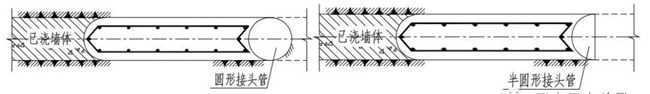
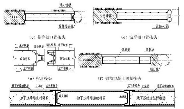
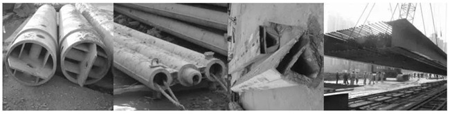
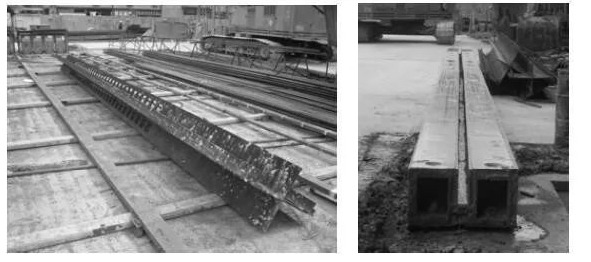
Commonly used flexible joints in engineering mainly include circular (or semi-circular) lock pipe joints, corrugated pipe (double corrugated pipe, triple corrugated pipe) joints, wedge joints, reinforced concrete prefabricated joints, and rubber water stop joints. The flat form of the joints As shown in Figure 11-9. Figure 11-10 is a physical picture of several types of joint pipes. Flexible joints have poor shear and bending resistance and are generally suitable for foundation pit projects that do not require high shear and bending resistance of construction joints in trench sections.
(1) Lock pipe joint
Circular (or semicircular) lock-mouth pipe joints and corrugated pipe (double-wave pipe, triple-wave pipe) joints are collectively called lock-mouth pipe joints. Lock-mouth pipe joints are the most commonly used joint form in underground continuous walls. Lock-mouth pipes are used When the underground continuous wall concrete is poured, it is used as a side form to prevent the concrete from flowing around. At the same time, a semicircular or corrugated surface is formed at the end of the trough section, which increases the seepage path of groundwater at the joints of the trough section. The lock pipe joint has a simple structure and strong construction adaptability, and the water-stopping effect can meet the needs of general projects.
(2) Reinforced concrete precast joints
Reinforced concrete precast joints can be prefabricated in the factory and shipped to the site, or they can be precast on-site. Prefabricated joints generally adopt an approximately I-shaped cross-section and replace the position and function of the lock pipe during the construction process of the underground diaphragm wall. There is no need to jack up the joint after it is placed, and it serves as a part of the underground diaphragm wall. Since the prefabricated joints do not need to be removed, the construction process is simplified and the efficiency is improved. It has advantages that conventional lock pipe joints cannot match. It is especially suitable for ultra-deep underground diaphragm wall projects where it is difficult to pull out the lock pipe. When restricted by factors such as transportation and hoisting equipment capacity limitations, prefabricated joints are generally hoisted in sections in the depth direction. The length of the sections should be determined according to the excavation depth of the foundation pit to ensure that the location of the section joints is a certain amount below the bottom of the foundation pit. Depth is the principle. The upper and lower sections can be connected by steel plate joints between prefabricated reinforced concrete square pile segmented piles, and the joints should be in a flat and dense connection state. The upper and lower sections of the prefabricated joint can also be fixed with bolts and connections first, and then welded.
(3) I-shaped steel joint
This joint form uses I-shaped steel plates spliced together as the construction joint. The flange steel plates of the profile steel are welded to the horizontal steel bars of the leading tank section. The joint steel bars in the subsequent tank sections can be set deep into the spliced steel plate area of the joint. There is no unreinforced area in this joint, and the underground diaphragm wall formed has good integrity. The concrete poured successively is separated by steel plates, which lengthens the bypass path for groundwater penetration and has good water-stopping performance. The construction of I-shaped steel joints avoids the process of pulling out the lock pipe or joint box in the construction of conventional groove section joints, greatly reducing the construction difficulty and improving construction efficiency. This joint was successfully used in the design of the cylindrical underground diaphragm wall of the Expo underground substation with a diameter of 130m and a digging depth of 34m. The I-shaped steel joint is shown in Figure 11-9(g).
3. Rigid joint
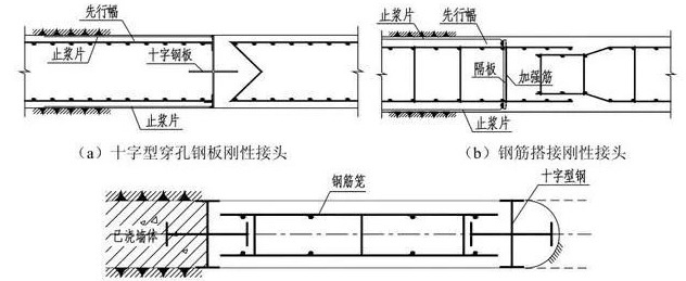
Rigid joints can transmit the vertical shear force between tank segments. Rigid joints are often used when rigid connections need to be formed between tank segments. The rigid joints used in engineering mainly include straight or cross-perforated steel plate joints, steel bar lap joints, and cross-shaped steel plug-in joints.
(1) Cross perforated steel plate joint
The cross-perforated steel plate joint is the most commonly used rigid joint form in underground diaphragm wall projects. It uses perforated steel plates to connect components between adjacent trough sections. The perforated steel plates form an embedding and interlocking effect with the concrete of the trough sections on both sides, which can withstand the underground The shear force on the vertical joints of the diaphragm walls makes the adjacent underground diaphragm wall trough sections form a whole to bear the vertical load of the superstructure, coordinating the uneven settlement of the trough sections; at the same time, the perforated steel plate joints also have good water-stopping properties. The cross steel plate joint is shown in Figure 11-11(a). This rigid joint is widely used in underground diaphragm wall design and the technology is relatively mature. Cross steel plate rigid joints are used in projects such as the Bank of Shanghai Building, Jiefang Daily News Center, Lanxin Apartment, and Shanda Center.
When using cross-perforated steel plate joints, the following issues should be noted:
a. To prevent side flow during concrete pouring and affect the construction of adjacent tank sections, cross-perforated steel plates should be installed along the depth of the tank section and should be embedded in the sediment at the bottom of the tank to a certain depth to completely block the flow path of the concrete. For tank sections that require a deeper underground diaphragm wall to isolate groundwater, the steel cage should be deepened to the bottom of the tank to fix the cross-steel plates.
b. When using cross-perforated steel plate rigid joints, if the wall steel cage is too long, the cross-perforated steel plate will easily bend and deform during the hoisting and settling process of the steel cage, making the cross steel plate unable to move smoothly down the joint box notch. Affects the sinking of the steel cage. Therefore, it is generally not suitable to use cross-perforated steel plate joints in ultra-deep underground diaphragm wall trough sections exceeding 40m deep.
c. When the underground diaphragm wall adopts “two walls in one”, to ensure the anti-seepage performance of the underground diaphragm wall, under the conditions of satisfying the stress, the cross steel plate perforations should be set below the base as much as possible to reduce the number of holes above the base of the underground diaphragm wall. Possibility of leakage.
(2) Steel bar lap joint
The steel bar overlap joint adopts the concave and convex overlap of horizontal steel bars in adjacent trough sections. The steel cages of the trough section are constructed first with overlapping portions extending from both sides. By taking construction measures, space for the overlapped steel bars can be left when pouring concrete. The trough section is constructed first. After it is formed, part of the steel cage of the subsequent construction trough section overlaps the steel bars extending from the preceding construction trough section, and then the concrete of the subsequent construction trough section is poured. The planar form of the steel bar lap joint is shown in Figure 11-11(b). This type of connection has underground diaphragm wall steel bars passing through the joint (horizontal steel bars and longitudinal main bars), making it a completely rigid connection. Relevant experimental studies have shown that its structural connection stiffness and joint shear resistance are superior to perforated steel plate joints. According to the “Guidelines for the Design and Construction of Underground Diaphragm Wall Foundations” issued by the Japan Road Association, based on the test results of different steel bar overlap lengths, steel bar ratios, and steel bar gaps, it is recommended that the unit allowable stress at the joints should be based on the allowable stress of the underground diaphragm wall. 80% comes from design.
(3) Cross steel plug-in joint
The cross-shaped steel plug-in joint welds two pieces of T-shaped steel on the I-shaped steel joint, and the T-shaped steel is anchored into the adjacent tank section, further increasing the flow path of groundwater, while enhancing the water-stopping effect, it also increases the shear resistance between wall segments ensures the underground continuous wall has good integrity. The cross-shaped steel plug-in joint is shown in Figure 11-11(c). Figure 11-12 is a physical picture of several rigid joints and joint boxes.
4. Principles for selecting construction joints
Since there are many types and quantities of underground continuous wall construction joints, in actual projects, on the premise of meeting the stress and water-stop requirements, construction joints with simple construction and mature technology should be selected based on regional experience to ensure the construction quality of the joints:
(1) Due to the convenient construction and simple structure of lock-mouth pipe flexible construction joints, in general projects, under the conditions of meeting the stress and water-stop requirements, lock-mouth pipe flexible joints should be used first in the construction joints of underground diaphragm wall trough sections; when underground diaphragm walls When it is difficult to pull out the lock pipe at the super deep top, it is recommended to use reinforced concrete prefabricated joints or I-shaped steel joints.
(2) When it is necessary to form a whole according to the structural stress requirements or when multiple wall segments jointly bear the vertical load and vertical shear force needs to be transmitted between the wall segments, rigid joints should be used between the trough segments, and the actual stress state should be determined to Check the bearing capacity of the tank section joints.
Thanks
