
Introduction to Anti-Slide Pile Construction Technology
1. What Are Anti-Slide Piles?
Anti-slide piles are structural columns that penetrate through a landslide mass and extend into the stable bedrock below. They counteract the sliding force of the slope, enhancing stability. These piles are primarily used for shallow to medium-thickness landslides and are a key slope stabilization measure.
Advantages of anti-slide piles include:
-
Reduced earthwork volume
-
Requires supporting mechanical equipment
-
Short construction period
-
Widely adopted in slope reinforcement projects
2. Function of Anti-Slide Piles
Anti-slide piles stabilize slopes by transferring the thrust of the sliding mass into the stable stratum below the slip surface. The resistance (anchoring force) provided by the embedded portion of the pile balances the sliding force, preventing slope movement.
Pile Material Selection:
Depending on factors such as landslide thickness, thrust magnitude, waterproofing requirements, and construction conditions, piles can be made of:
-
Timber
-
Steel
-
Concrete
-
Reinforced concrete
Embedment Depth Guidelines:
-
Soft rock: 1/3 of the designed pile length
-
Hard rock: 1/4 of the designed pile length
-
Soil slip surface: 1/2 of the designed pile length
-
Sliding along bedrock: 2–5 times the pile diameter
Pile Arrangement:
-
Continuous pile rows
-
Spaced pile rows
-
Lower-spaced, top-connected rows
-
Anchored piles with intermittent spacing
Spacing: Typically 3–5 times the pile diameter to prevent soil slippage between piles.
Anti-Slide Pile Construction Process
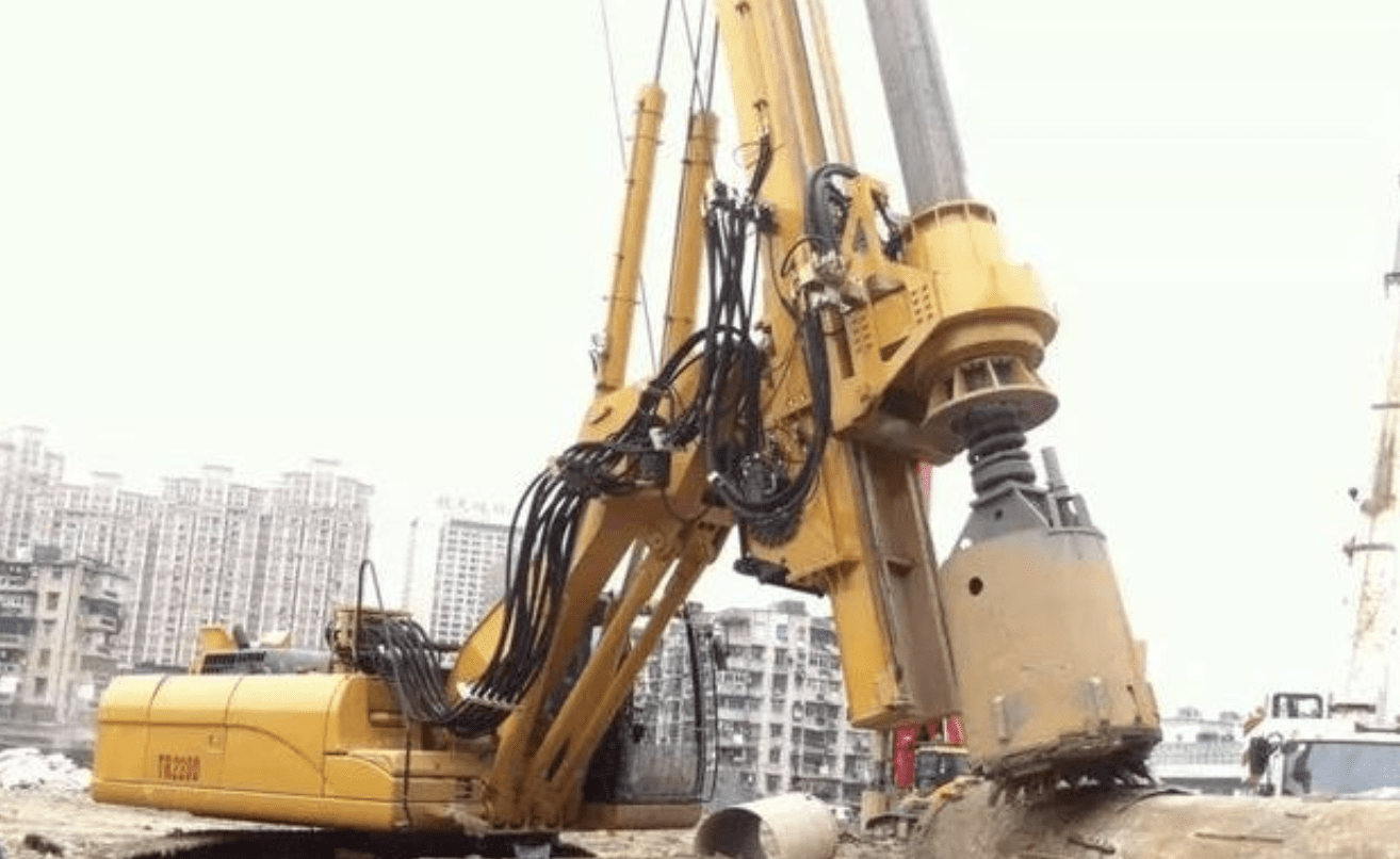
1. Rotary Drilling Pile Construction Workflow
2. Site Preparation
(1) Setting Out Pile Positions
-
After platform construction, use the total station coordinate layout to determine pile locations.
-
Set guide piles 200 cm from the casing edge along longitudinal and transverse axes.
-
Follow railway construction surveying standards with dual verification.
(2) Steel Casing Installation
-
Excavate and install the casing, backfilling with compacted clay.
-
Allowable deviation: ≤5 cm horizontally.
-
Casing depth: 1.5 m below ground; top elevation: 0.4 m above ground.
-
Verify verticality (≤0.5%) using guide piles.
(3) Drilling Rig Positioning
-
Place the rig on a stable, level surface.
-
Check alignment using a plumb bob and cross-reference guide piles.
-
Ensure the drill bit, rod, and pile centerline are vertically aligned.
3. Rotary Drilling
(1) Initial Drilling
-
Inject clean water into the casing.
-
Begin with slow drilling to create slurry.
-
Reduce speed near the casing base to stabilize the formation.
-
Resume normal drilling after advancing 5 m beyond the casing.
(2) Slurry Monitoring
-
Test slurry properties every 2–3 hours.
-
Continuously check drill rig levelness.
(3) Formation Adaptation
-
Collect cuttings to assess strata.
-
Adjust drilling speed, pressure, and slurry properties based on ground conditions.
-
Maintain a 1.5–2.0 m higher slurry level than external water to prevent wall collapse.
(4) Continuous Drilling
-
If paused, withdraw the drill bit and maintain slurry levels to stabilize the borehole.
4. Hole Cleaning
Upon reaching design depth:
-
Inspect hole diameter, depth, and shape using a caliper.
-
Obtain engineer approval before cleaning.
Cleaning Method:
-
Use reverse circulation to remove slurry and cuttings.
-
Clean casing walls simultaneously.
Acceptance Criteria:
-
Slurry density ≤1.1, sand content <2%, viscosity 17–20 s.
-
Sediment thickness: ≤5 cm (end-bearing piles) or ≤20 cm (friction piles).
Secondary Cleaning (if needed):
-
Use airlift reverse circulation via the tremie pipe.
-
Proceed to concreting immediately after approval.
5. Reinforcement Cage Fabrication & Installation
Fabrication:
-
Prefabricate in sections (standard length: 12 m; final section adjusted).
-
Number sections for proper alignment during assembly.
-
Install sonic tubes in the bottom section; pre-bind others.
Installation:
-
Transport using a flatbed with a dedicated cradle.
-
Hoist into place with a 16-ton crane.
-
Align sections vertically; splice main bars via arc welding.
-
Weld four extended bars to the casing top to prevent buoyancy during concreting.
6. Underwater Concrete Pouring
Key Preparations:
-
Ensure backup equipment and materials are available.
-
Complete pouring within ≤6 hours.
Tremie Pipe Specifications:
-
Diameter: 30 cm (tolerance ±2 mm).
-
Sections: 3 m long (bottom section: 4 m).
-
Lower smoothly to avoid cage/formation contact.
Initial Pour:
-
Maintain 35–40 cm between the pipe tip and the hole base.
-
Use a “cut-ball” method; ensure ≥1 m initial embedment depth.
Continuous Pouring:
-
Replace the 8 m³ hopper with a 2 m³ hopper after the first pour.
-
Maintain pouring speed ≥50 m³/h.
-
Monitor concrete rise; lift pipes incrementally.
-
Keep tremie embedded 1.5–5 m in fresh concrete.
Completion:
-
Overpour by ≥1 m above design elevation.
-
Remove excess during pile cap construction.
7. Key Documentation
-
Rotary drilling logs (speed, strata, special measures).
-
Slurry test records (every 2 hours).
-
Post-drilling checks (hole diameter, verticality).
-
Cleaning duration and slurry parameters.
