1. Introduction
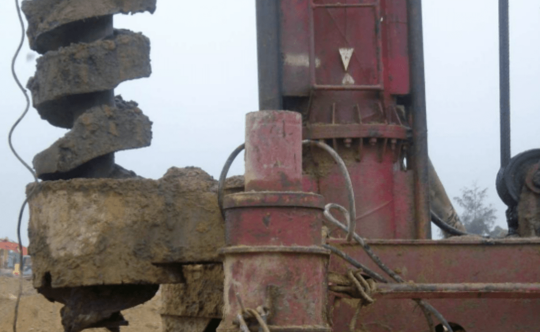
The long spiral drilling pumping super-fluid concrete with post-placement reinforcement cage technology evolved from Japan’s CIP (Cast-In-Place) method. Unlike conventional bored piles, this technique involves drilling to the designed depth using a specialized long spiral drilling machine, continuously pumping super-fluid concrete into the borehole through the drill head’s discharge valve until reaching the pile top, and then inserting the reinforcement cage to form the pile.
This innovative foundation construction method is widely applicable, unrestricted by groundwater levels. The super-fluid concrete exhibits excellent flowability and aggregate dispersion. The spiral drill rig serves dual purposes—drilling and concrete pumping—ensuring operational efficiency, rapid concrete placement, high-quality pile formation, and cost reduction. Recognized as one of the top ten construction technologies promoted by the Ministry of Construction in 2005, it has gained widespread adoption.
2. Technical Features
2.1 Superior Concrete Performance
-
Super-fluid concrete maintains high flowability, preventing aggregate segregation and ensuring uniform suspension.
-
Easy reinforcement cage insertion due to minimal resistance.
2.2 Enhanced Construction Quality
-
Eliminates issues like false bottoms, necking, pile breakage, and borehole collapse.
-
Ensures consistent pile integrity and load-bearing capacity.
2.3 High Efficiency and Adaptability
-
Capable of penetrating hard soil layers with high single-pile bearing capacity.
-
Fast construction speed with simplified operations.
2.4 Eco-Friendly Construction
-
Low noise and vibration, minimizing community disturbance.
-
No need for slurry wall protection, eliminating mud discharge and soil displacement.
2.5 Cost-Effective Solution
-
Lower overall project costs compared to conventional pile types.
2.6 Design Methodology
-
Follows dry-hole bored pile design principles.
-
Design parameters should align with dry-hole bored piles (higher than slurry-supported piles but lower than precast piles).
3. Applications
This method is suitable for:
-
Building and structuring foundation piles.
-
Retaining piles for excavations and deep foundations.
-
Various soil conditions, including fill, silt, sand, and gravel layers.
-
Water-bearing strata, soft soil, and quicksand zones.
-
Typical pile diameters range from 500mm to 800mm.
4. Technical Principle
The process involves:
-
Drilling to the designed depth using a long spiral drill rig.
-
Pumping super-fluid concrete through the drill pipe while retracting the drill.
-
Placing the reinforcement cage into the fluid concrete.
-
Overfill the pile top by 50cm to ensure adequate concrete strength.
5. Construction Process
6.1 Reinforcement Procurement and Testing
-
Material Inspection: Upon arrival, reinforcement must undergo quality checks, including physical properties, dimensions, and visual inspection.
-
Sampling: Samples are collected per standards, labeled with batch numbers, and tested under the supervision of the supervising engineer.
-
Non-Conforming Materials: Failed samples trigger double-sampling retests. Rejected materials are marked for downgrade or disposal.
6.2 Equipment Selection
-
Primary Machinery: Track-mounted long spiral drilling rig.
-
Auxiliary Equipment: Vibratory hammer, medium excavator, and loader.
6.3 Survey and Pile Layout
-
Establish control points based on the provided benchmarks.
-
Mark pile positions with steel pegs or bamboo markers, verified by surveyors.
-
Set reference piles every ten positions for alignment checks.
6.4 Drilling Process
-
Alignment: Ensure drill verticality within 20mm deviation using dual plumb bobs.
-
Speed Control: Maintain 1–1.5 m/min drilling rate; halt for issues like bit blockage or deviation.
-
Spoil Removal: Excavated soil must be cleared promptly.
-
Depth Verification: Confirm design depth and strata with supervising engineers.
6.5 Concrete Pumping and Pile Formation
-
Pump Setup: Minimize pipe bends for smooth concrete flow.
-
Concrete Quality: Slump must be 180–220mm; reject non-compliant batches.
-
Continuous Pouring: Match pump speed with drill withdrawal (2.5 m/min).
-
Testing: Collect cube samples (150×150×150mm) per shift for 28-day strength tests.
6.6 Reinforcement Cage Fabrication
-
Assembly Sequence: Fix main bars to stiffening rings, then weld spiral ties.
-
Welding Standards: Lap joints require 5d (bar diameter) length with full penetration.
-
Inspection: Cages must pass dimensional and weld checks before use.
6.7 Cage Insertion
-
Integrated Process: Insert the cage within 3 minutes post-concreting to prevent setting.
-
Alignment: Use a vibratory hammer for penetration (1.2–1.5 m/min), ensuring verticality via dual plumb lines.
-
Final Positioning: Confirm elevation with a level before extracting the drill pipe.
6.8 Construction Documentation
-
Maintain real-time logs for each pile, verified by the site supervisor.
6.9 Pile Head Cleanup
-
Remove excess spoil without damaging the pile or cage.
6.10 Pile Testing
-
Conduct integrity and load tests 28 days after concreting, selecting piles in consultation with the client and supervisor.


