
Reinforcement Cage Fabrication
Fabrication Methods
According to the “Highway Engineering Quality Inspection and Evaluation Standards,” the allowable deviations for reinforcement cage fabrication are:
| Item | Description | Allowable Deviation (mm) |
|---|---|---|
| 1 | Main reinforcement spacing | ±20 |
| 2 | Stirrup or spiral reinforcement spacing | ±10 |
| 3 | Reinforcement cage diameter | ±5 |
| 4 | Reinforcement cage length | ±10 |
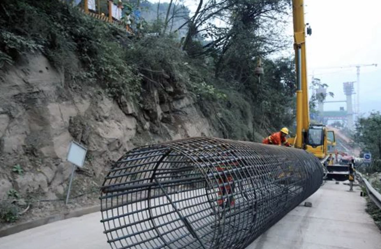
The reinforcement cage should be formed using stiffening rings approximately every 2 meters. These rings are placed inside the main reinforcement and reinforced with triangular internal supports. Main reinforcement bars are spot-welded to the outside of stiffening rings, maintaining perpendicularity, before binding stirrups.
Key Fabrication Requirements
-
Welding Specifications: Main reinforcement requires 10D double-sided welding. In practice, welds should be extended by 1cm to compensate for potential imperfections at start/stop points.
-
Joint Staggering: Reinforcement joints must be staggered according to specifications.
-
Stiffening Ring Welding: Butt welding produces excellent results for stiffening rings and should be widely adopted.
Sectional Fabrication Considerations
Due to length, weight, and drilling rig height limitations (typically under 10m), reinforcement cages are fabricated in sections. Key points:
-
Minimum section length: 6m (optimally matching standard reinforcement lengths)
-
50% of joints must be staggered during connection
-
Maintain straight alignment of reinforcement axes
-
Consider welding length in total cage length calculations
-
Flaring the bottom reinforcement slightly prevents the cage from floating and snagging on the tremie pipes
Welding Quality Control
Night work requires special attention to weld integrity. Key considerations:
-
Use specified electrode types
-
Vertical welding presents challenges (including electrical safety risks)
-
Avoid main reinforcement burn-through through:
-
Improved welder skills (consider welding competitions)
-
Avoiding excessive current for speed
-
Supervisor accountability
-
Advanced Connection Technology: Sleeve Thread Connection
Advantages:
-
Superior construction quality
-
Material savings (compared to 10D welding)
-
Labor efficiency in welding operations
Cost Considerations:
Conduct a detailed cost-benefit analysis comparing:
-
Labor costs
-
Equipment expenses
-
Power consumption
-
Material usage
-
Work efficiency
Implementation Notes:
-
Cut reinforcement ends squarely
-
Mark reinforcement for proper alignment
-
Ensure sufficient workspace for pre-assembly
-
Control thread depth (neither too tight nor loose)
-
Grind reinforcement ends for a better fit
Quality Control Measures:
-
Precise thread processing
-
Reinforcement and preparation
-
Alignment marking
-
Proper thread depth control
Ultrasonic Testing Tube Installation
Options:
-
Standard welded connection
-
Screw-nut connection (recommended):
-
5x faster installation
-
No special equipment required
-
Weather-resistant
-
Reduced labor skill requirements
-
Minimal material waste
-
Installation guidelines:
-
Length matches the reinforcement cage
-
Bottom tube extends 20-30cm beyond cage base
-
Fill with clean water before sealing
-
Prevent tube blockage
Protection Layer Setup
Optimal protection uses concrete rotary pads:
-
The thickness matches the required concrete cover
-
Spaced every 2m (4 pads per ring)
-
Welded to the main reinforcement
Installation improvements:
-
Use prefabricated mortar pads with center holes
-
Insert stirrup-grade reinforcement through holes
-
Spot-weld to main reinforcement
-
Install during cage lowering for a rolling effect
Benefits:
-
Maintains cage centering
-
Ensures proper cover
-
Minimizes borehole wall damage
Reinforcement Cage Storage
Proper storage requirements:
-
Level, dry storage area
-
Wooden blocks under stiffening rings to prevent soil contact
-
Clear section numbering/labeling
-
Protection from rain and rust
-
Organized sequential arrangement
Lifting and Positioning Quality Control
Lifting Procedures
-
Use the two-point lifting method:
-
First point: Lower section
-
Second point: Midpoint to upper third
-
-
Lift the first point slightly, then both simultaneously
-
After clearing the ground, release the first point gradually
-
Check alignment when vertical
Positioning Process
-
Lower slowly without borehole contact
-
Temporary supports at the borehole mouth:
-
Use steel sections through stiffening rings
-
-
Section connection:
-
Maintain vertical alignment
-
Weld sequentially
-
-
Final positioning:
-
Calculate positioning reinforcement elevation
-
Use parallel I-beams (30cm wider than the tremie diameter)
-
Weld to casing with 4φ25 short bars
-
-
Center alignment:
-
Use crosslines to locate the cage center
-
Align with the pile center using reference markers
-
For partial reinforcement piles:
-
Secure the top suspension ring with channel steel
-
Weld firmly to prevent sinking
Preventing Reinforcement Cage Flotation During Concrete Placement
Primary Causes
-
Tremie pipe snagging during withdrawal
-
Solution: Replace cross bracing with triangular supports
-
-
Concrete uplift force exceeding cage weight
-
Critical zones:
-
Tremie outlet 1-3m below the cage bottom
-
Concrete surface within 1m of the cage bottom
-
-
Control Measures
-
Reduce placement speed to <0.5m/min rise in critical zones
-
Proper tremie positioning:
-
Avoid proximity to the cage top
-
-
Adjust tremie embedment:
-
Reduce to 4m after the concrete covers the cage
-
-
Concrete quality control:
-
Maintain proper slump
-
Ensure continuous placement
-
-
Monitoring:
-
Observe suspension reinforcement for movement
-
-
Correction methods:
-
Slow placement speed
-
“Slow lift-quick drop” tremie movement
-
Common Issues and Solutions
Frequent Problems
-
Cage flotation
-
Partial cage falling
-
Positioning inaccuracy
-
Deformation
-
Testing tube blockage
Falling Prevention
-
Strengthen lifting points:
-
Additional short reinforcement welding
-
-
Proper stirrup:
-
Correct spacing
-
Secure binding
-
-
Lifting precautions:
-
Use four equal-length slings (never folded pairs)
-
Two-point lifting method
-
Vertical movement only
-
Slow borehole entry
-
Alignment Control
-
Use reference piles
-
Sequential fabrication:
-
Match sections during production
-
Clear numbering system
-
-
Positioning aids:
-
Ear reinforcement
-
Concrete rotary pads
-
-
Main reinforcement straightness control
This comprehensive guide covers all critical aspects of reinforcement cage handling for pile foundation construction, ensuring quality, safety, and efficiency in your projects.
