
Introduction
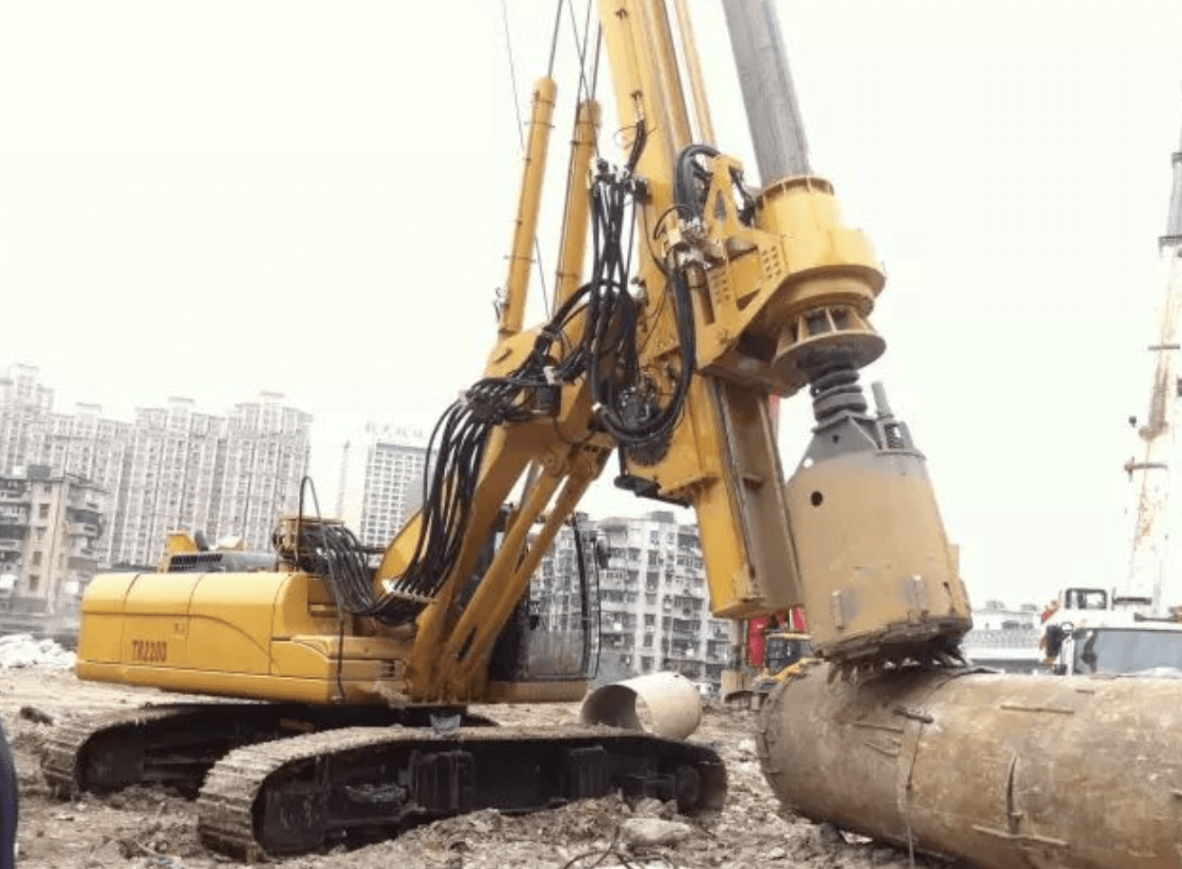
Rotary drilling rigs have seen widespread application in China in recent years for cast-in-place pile construction. As a core drilling equipment, the operational process involves seven basic actions: positioning, lowering the drill, drilling, lifting the drill, rotating, shaking off soil, and returning to position.
During the lifting operation, drill rods are typically retracted sequentially from the innermost to the outermost section. However, under certain conditions, rods may retract out of sequence—a phenomenon known as “rod sticking” (or “带杆” in Chinese). This occurs when an outer rod section retracts before its inner counterpart, indicating jamming or improper engagement between sections.
Rod sticking, while originating in the drill rods, can cause extensive damage to multiple rig components. Understanding its mechanisms, mitigating its destructive effects, and developing solutions to prevent it are critical for operational safety and efficiency. This article explores the causes, impacts, and improvement strategies for rod sticking.
1. Mechanisms of Rod Sticking
Both friction-type drill rods and mechanically locked drill rods can experience rod sticking, though the latter is more prone to it.
1.1 Mechanically Locked Drill Rods
These rods are used in hard formations due to their high pressure capacity. However, lifting requires an unlocking step—rotating the drill bucket counterclockwise to disengage the pressure platform before retracting.
Unlocking can result in three states:
-
Full Unlock (Fig. 1.2A): All pressure platforms disengage, rods retract sequentially with a “nodding” sensation—no rod sticking occurs.
-
Partial Unlock (Fig. 1.2B): Some pressure platforms remain engaged, causing intermittent nodding. This is the most dangerous state, as rods may suddenly drop, damaging the powerhead.
-
No Unlock (Fig. 1.2C): Rods lift without retracting, easily detectable and correctable by lowering and reattempting unlocking.
Secondary Rod Sticking: Even fully unlocked rods can re-engage during lifting due to:
-
Wire rope tension changes cause rotation.
-
Mud turbulence induces reverse rotation in drill tools.
Solution: Continuously rotate the drill counterclockwise while lifting to minimize re-engagement.
1.2 Friction-Type Drill Rods
These rods rely on friction between the inner and outer keyways to transmit pressure. Rod sticking occurs due to jamming, caused by:
-
Gaps (Δ1, Δ2 ≈ 10–20 mm) between keyways allow debris (sand, or loose hardware) to lodge.
-
Wear-induced deformities (e.g., burrs ) creating “wedge gaps” that trap particles.
Critical Particles: Only particles close to gap sizes (“opportunity particles”) cause jamming. Regular maintenance and clean drilling fluid reduce this risk.
2. Destructive Effects of Rod Sticking
2.1 Severity Classification
-
Grade 1 (Severe): Innermost rods jam; outer rods free-fall upon sudden release, causing catastrophic impact.
-
Grade 2 (Moderate): Mid-level damage, often fatiguing components.
-
Grade 3 (Minor): Negligible immediate impact but contributes to long-term wear.
2.2 Impact Forces (Case Study: 22 TM Rig)
-
Free-fall energy (Wd): 87,365 kg·m at 57.2 km/h.
-
Buffer capacity (Wh): 1,517 kg·m—only 1.7% of Wd, grossly insufficient.
-
Shock multiplier (η): 14.6–364× normal force, risking structural failure.
2.3 Component Damage
-
Powerhead Buffer: Rubber dampers deform;护圈 bends.
-
Pressure Cylinder: Hydraulic locks fail; pistons detach or耳轴 fractures.
-
Gearbox: Housing cracks under severe冲击.
-
Large Structures (Mast, Boom): Welds tear from dynamic loads.
-
Fatigue Effects: Bolts loosen; wire ropes snap.
3. Mitigation Strategies
3.1 Passive Prevention
-
5-Stage Damping:
-
Rod rubber pads
-
Heavy springs
-
High-elastic rubber
-
Special dampers (e.g., leopard tank tech)
-
Large flexible systems
Current buffers are inadequate for rod sticking; redesigns face practical challenges.
-
3.2 Structural Reinforcements
-
Gearbox Mounts: Strengthen “square-to-round” and base frames.
-
Pressure Cylinders: Enhance piston joints; use multi-stage relief valves.
-
Boom Connections: Reinforce welding against dynamic loads (Fig. 3.2).
3.3 Operational Best Practices
-
Lift + Rotate: Always rotate counterclockwise while lifting to prevent re-locking.
-
Training: Improve operator vigilance and response protocols.
3.4 Active Prevention (Drill Rod Design)
-
Anti-Jamming Features: Learn from leaders like Bauer.
-
Visual Aids: Color-coded lifters or cameras to assist operators.
-
Smart Controls: San Heavy Machinery Co.’s proprietary solution (undisclosed).
4. Conclusion
Rod sticking poses significant risks to rotary drilling rigs, but its effects can be mitigated through mechanical improvements, operational discipline, and advanced design. Industry progress—particularly in smart controls—promises a future where rod sticking is eradicated, ensuring safer, more efficient operations.
